
This is my version of a home made ground mount HF multi band antenna that covers 10m, 12m, 15m, 17m, 20m, 30m, and 40m. They are a really simple design and are easy to work on since they do not require a tower. This design is not mine and I give full credit to M0MCX (Callum McCormick) for his commercially available DX Commander and to PG5M (Gerben Menting) whose website I referenced 100% to make my version of this multi band. Callum has a youtube channel that I highly recommend anyone to subscribe to and watch his series. He is an excellent teacher and explains antenna physics for these multi band antennas in a way anyone can understand. In the spirit of amateur radio, I am a full believer in making your own equipment if you can. I love to learn and really enjoy building things that actually work and are useful. Its quite a feeling of accomplishment.
The first thing I did was to read the entire PG5M website and printed all his drawings and instructions for his HF multi band. I also watched Callums YouTube videos on his DX Commander series videos and also downloaded the DX Commander assembly instructions and read all those. Next was to make a list of parts I needed to make one of these antennas. There are a many ways to make this antenna and you can substitute parts for whatever you have around in your shop or garage. The most expensive items are the support pole and the wire. The remaining items are cheaper items that you can get off amazon or local hardware store.
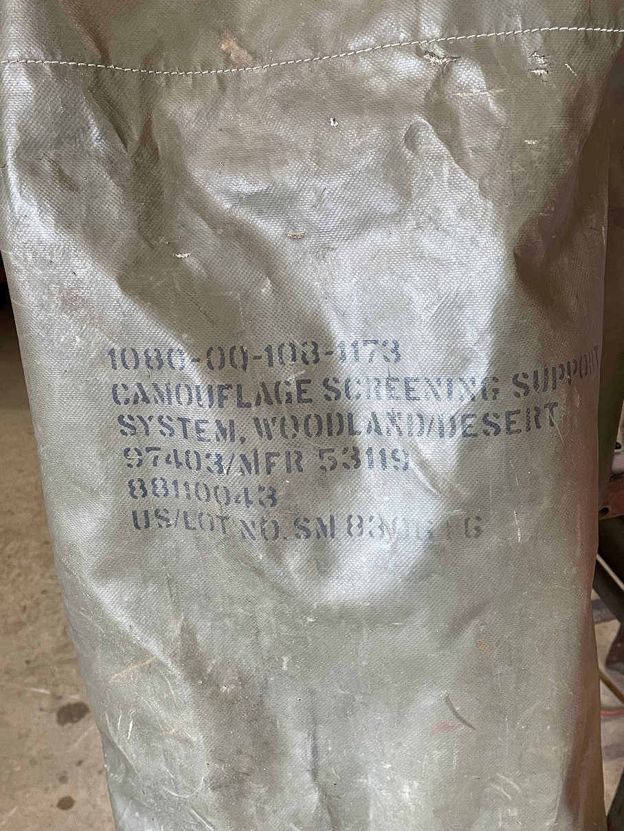
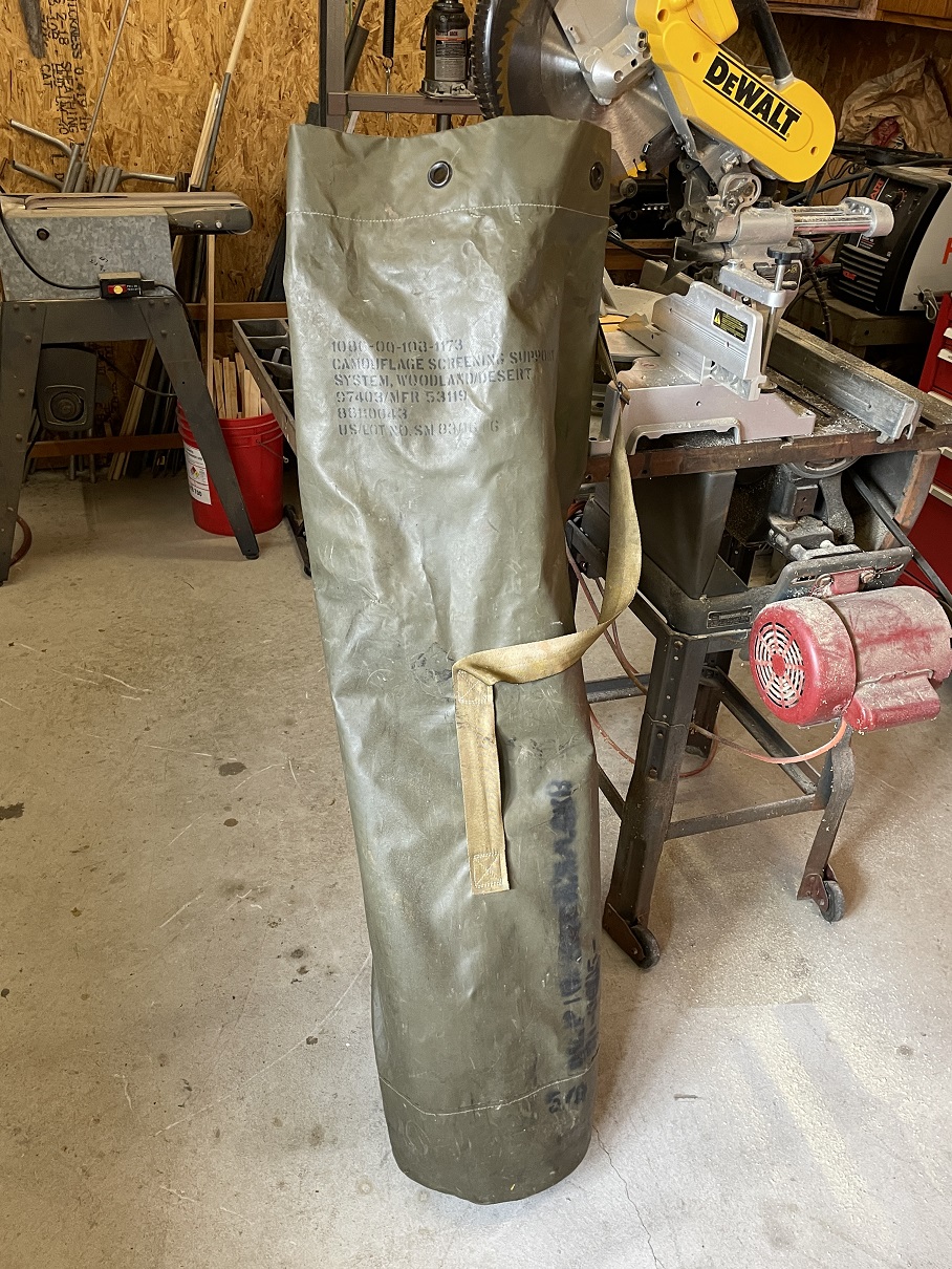
The Support Pole: All the reference designs use the carbon fiber extendable pole. I have seen these used as flagpoles at campgrounds and also for various antennas. They cost around $80 and you can in fact buy one direct from the DX commander website or if your in the USA DX Engineering carries them. I did not have one available but I did run across a fiberglass tent pole kit at a local Army Surplus store. These poles were heavy duty and most importantly not metal (conductive). $49 and the kit was mine.
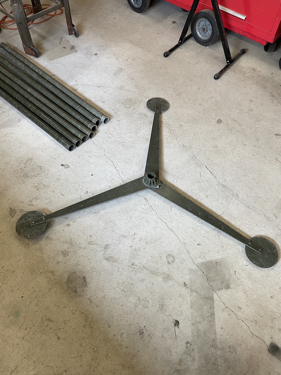
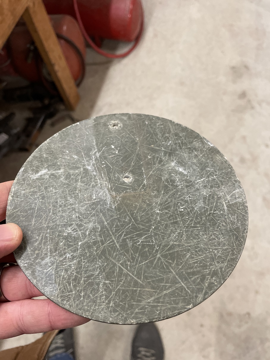
I received 12 interlocking poles at 4ft each and 6 of these 3 leg base ground supports. All made of green fiberglass. The ground supports have round disks as feet and I will totally use those for the “spacers” needed to separate the antenna wires. I ground off the rivets that held them on and they easily separated from the legs.
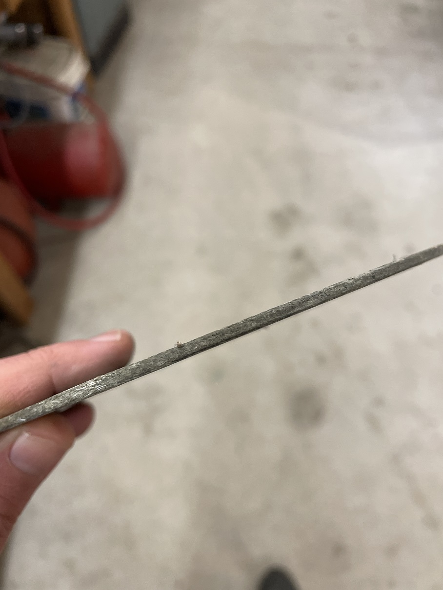
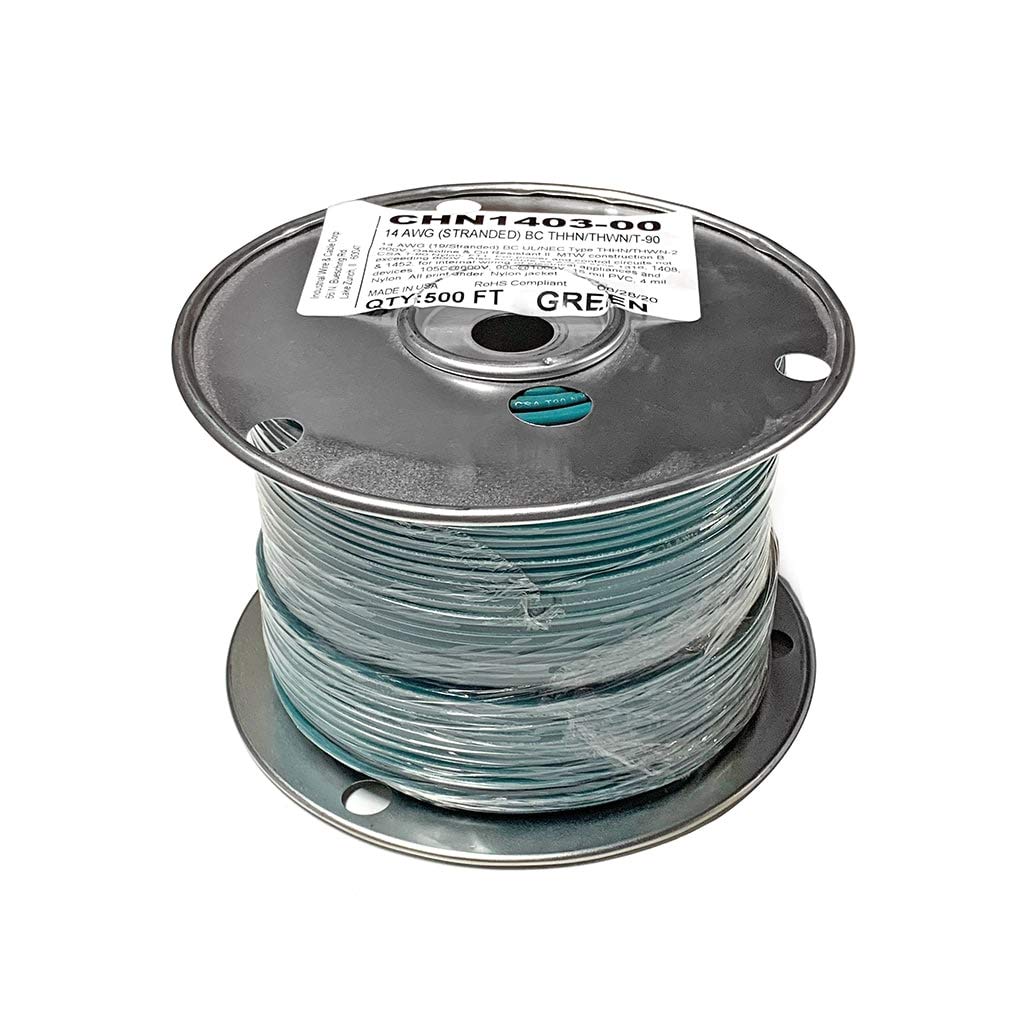
Wire: I recommend a 14 AWG copper stranded wire. Anything will work but the larger the better for handling power and robustness for outside. 14 AWG easily handles my Heathkit SB-200 amp. I had a 500ft roll of THHN/THWN 600 volt wire using in electrical wiring. Its pretty stiff and the PVC insulation is not the greatest for UV sunlight but I used it and it works just fine. DX Engineering sells really nice antenna wire in bulk if you need to buy some. They also sell the DX Commander antenna wire which is very good quality.
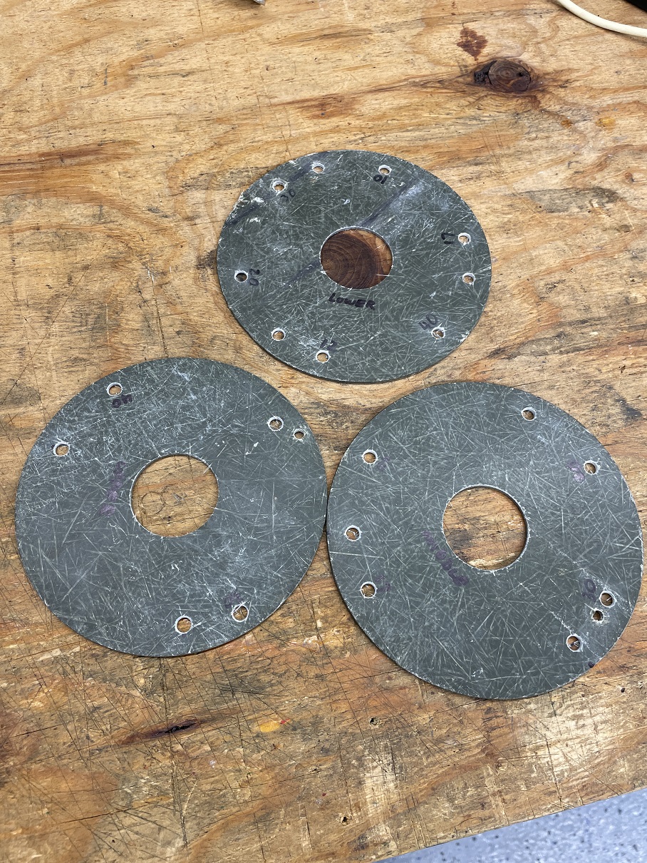
Base Plates and Spacers: I used 0.250″ thick aluminum for the base plates for my antenna. I had this in my junk pile so its what I used. I literally traced PG5M’s base plate drawings onto my aluminum with a black Sharpe marker. I cut them all out with a hand jig saw with a fine metal cutting blade.
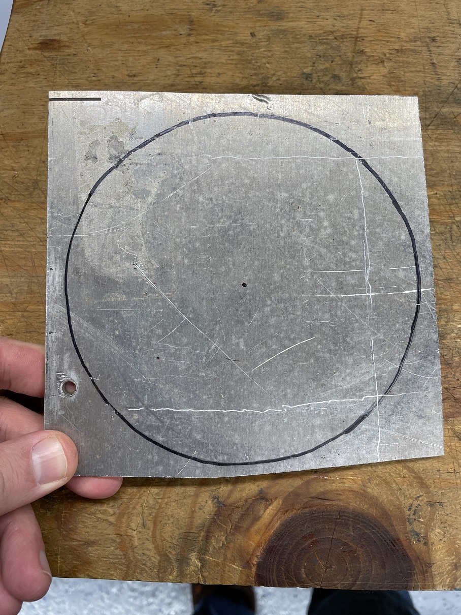
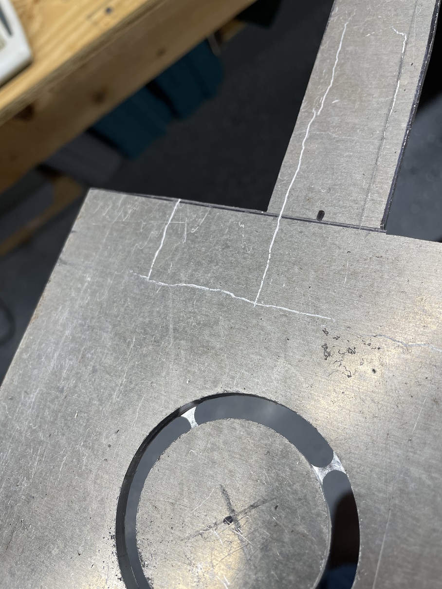
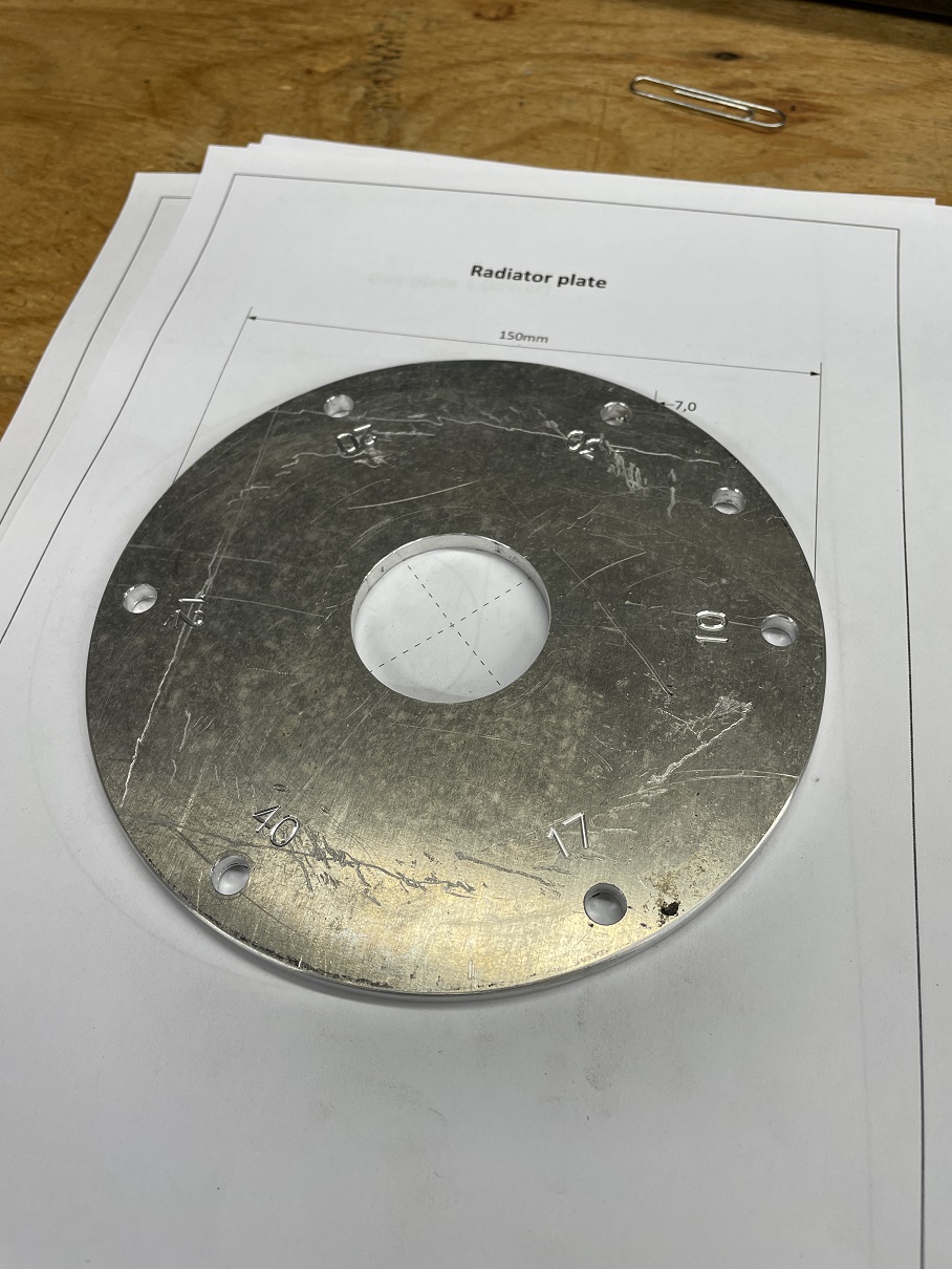
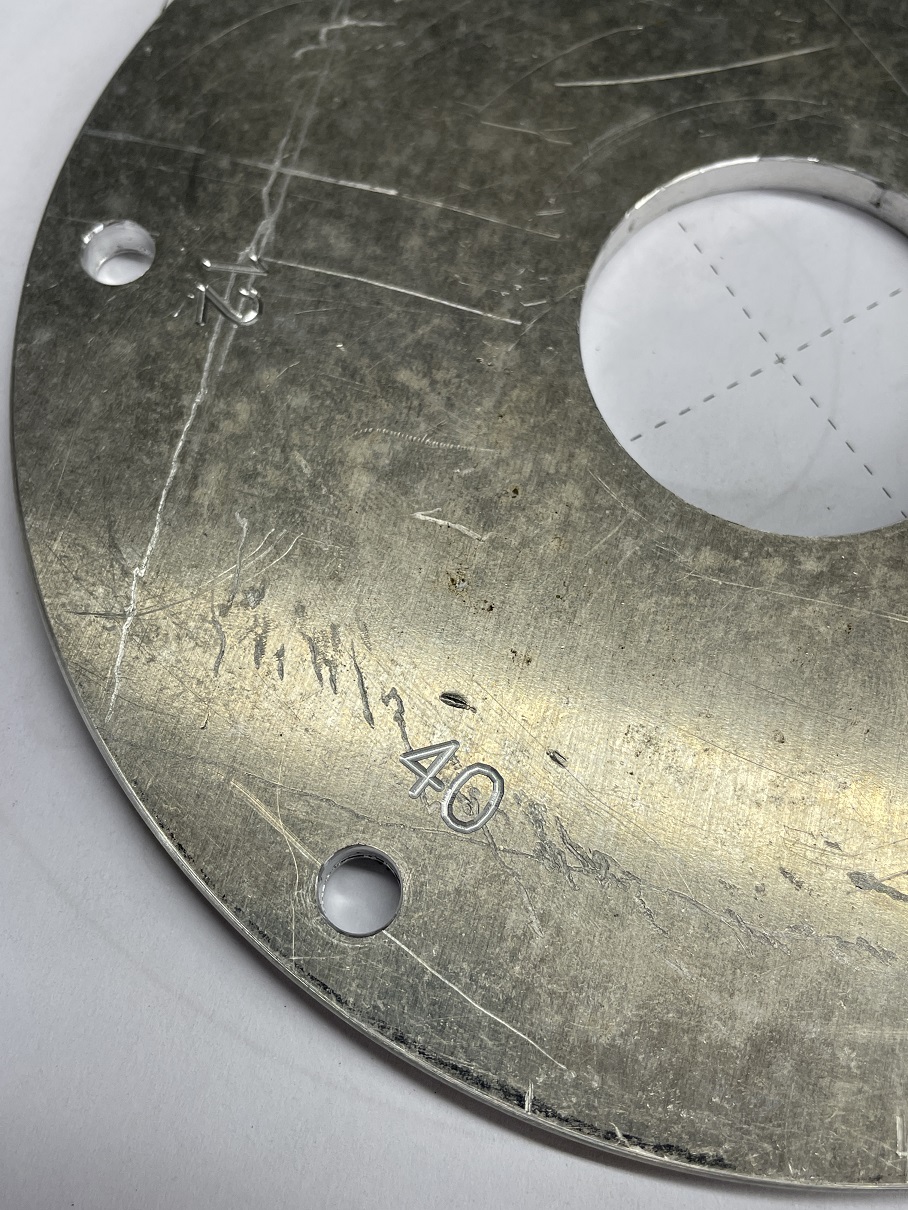
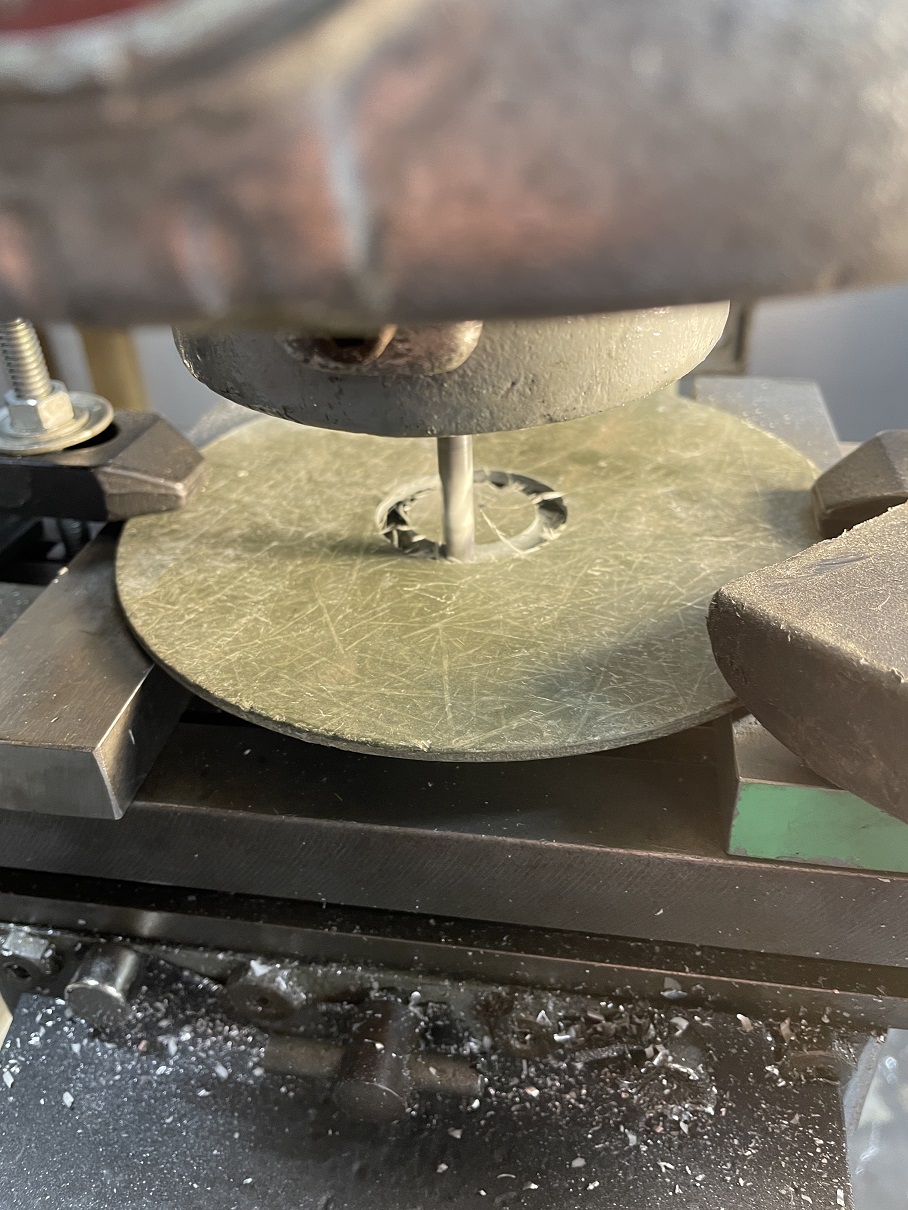
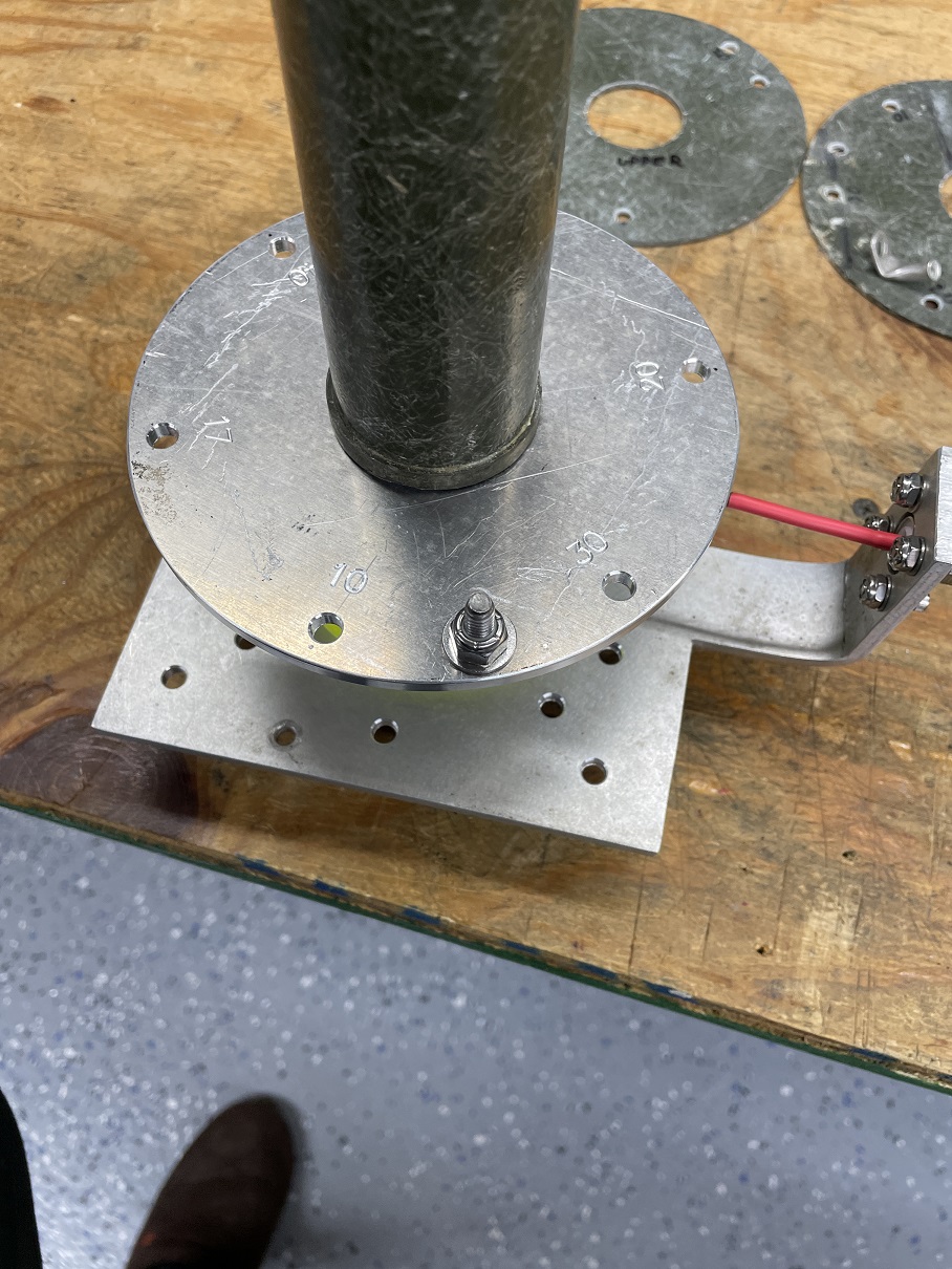
I have both a lathe and CNC Mill in my shop so I cleaned everything up and bored all the holes with them. No worries if you don’t have a lathe or mill. A hand drill or drill press and a hole saw will work just as well. PG5M used a file to smooth all his edges. It takes longer but the result is satisfactory. Use whatever tools you have at your disposal. I used the CNC to engrave the bands next to each hole in my base plate. I highly recommend you label everything as this makes assembly and future maintenance easy. Stickers or a good paint pen work on these parts as well.
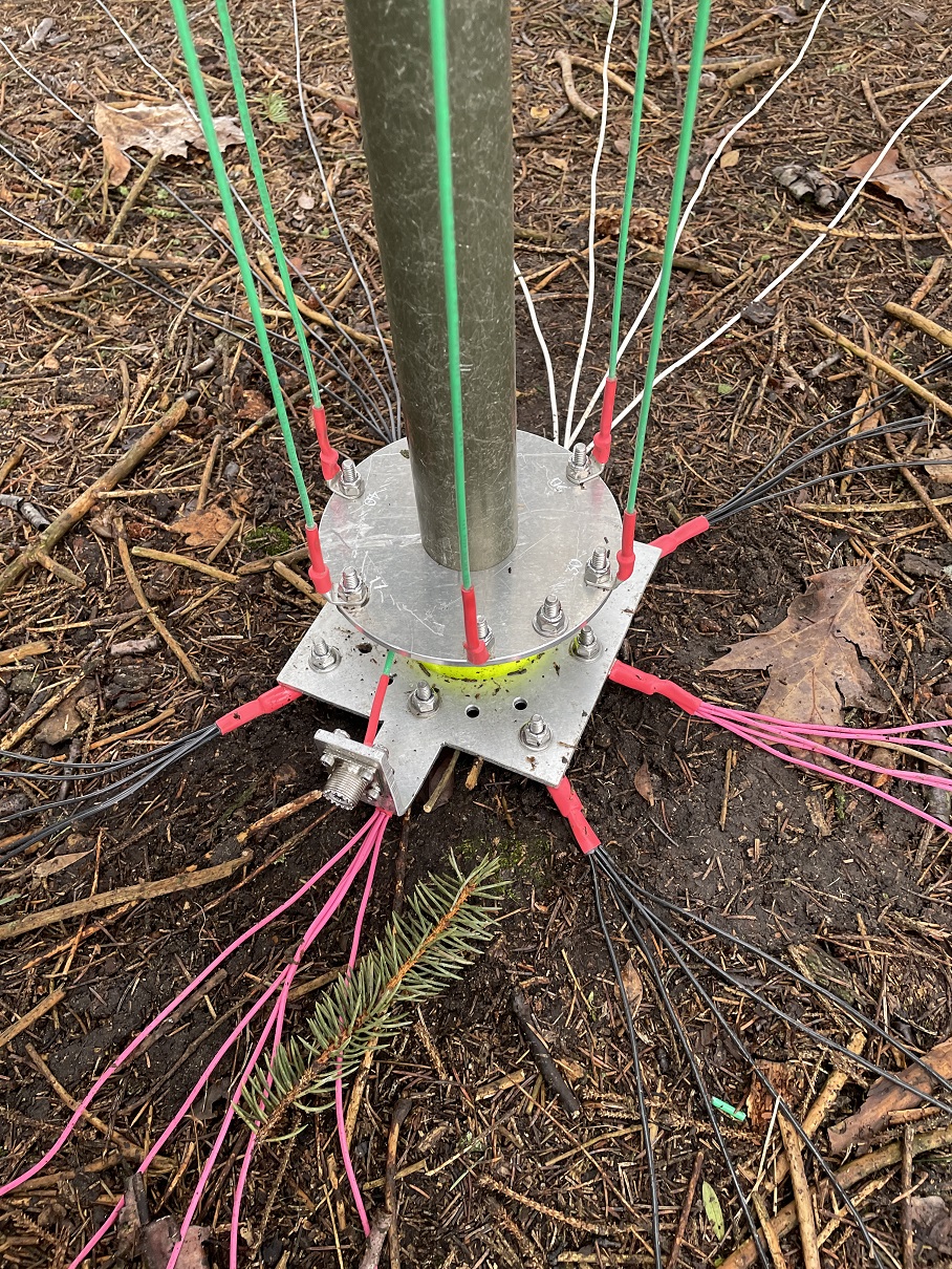
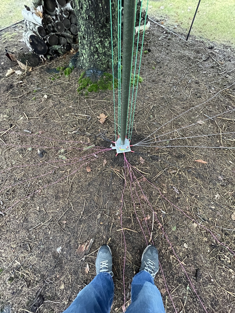
Assembly of the Base Mount: My Base mount is held together by the force of all the shock cords that pull the antenna wire tight. No glue or clamps are used to fasten it together. In reality, once assembled its very hard to disassemble. Those shock cords really hold it tight.
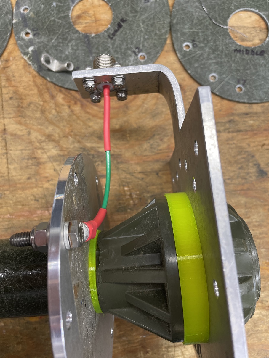
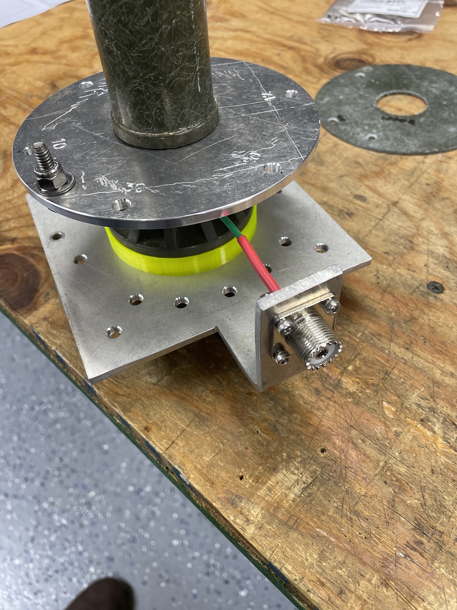
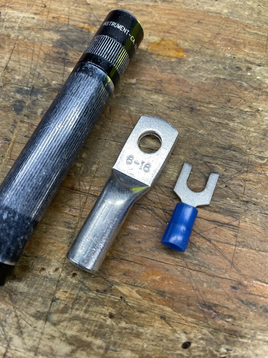
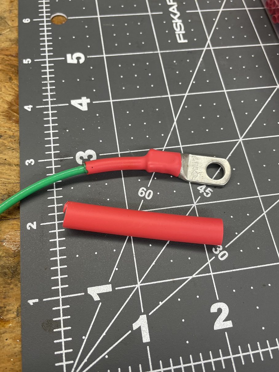
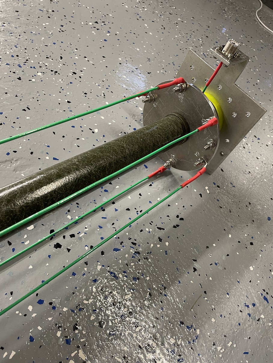
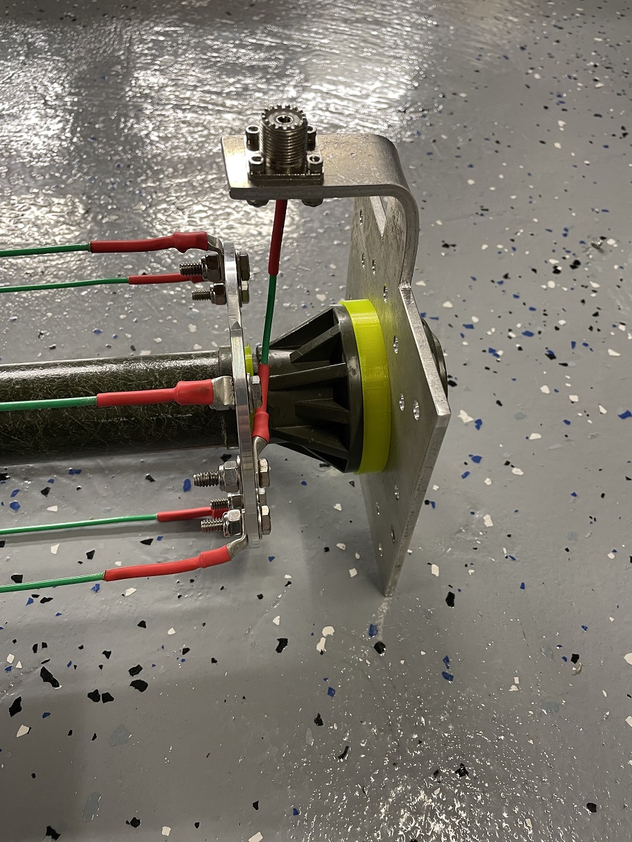
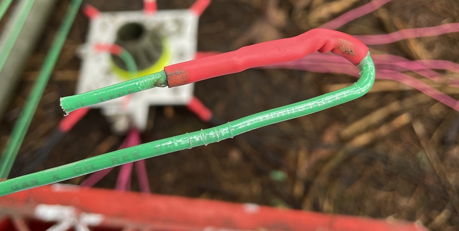
I used the 3 legged ground support center pieces that came with my tent pole kit. They were used to hold the poles and they worked perfect for my metal base plates. I had some gaps to deal with so I just 3D printed some spaces out of TPU filament (yellow parts shown in photos). Fastening all the antenna wire to the main feed plate requires soldering and heavy duty wire lugs. I used 8 AWG copper lugs for M6 bolts (nickel plated). I bought straight ones and bent them into a “L” shape with a vise. They were super easy to bend with pliers. Don’t use the wimpy crimp ones at the auto parts store if you want this antenna to last.
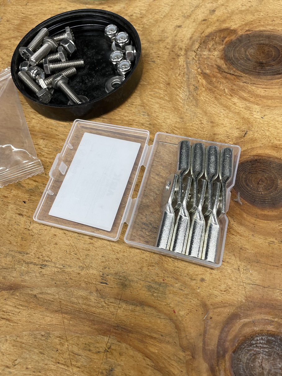
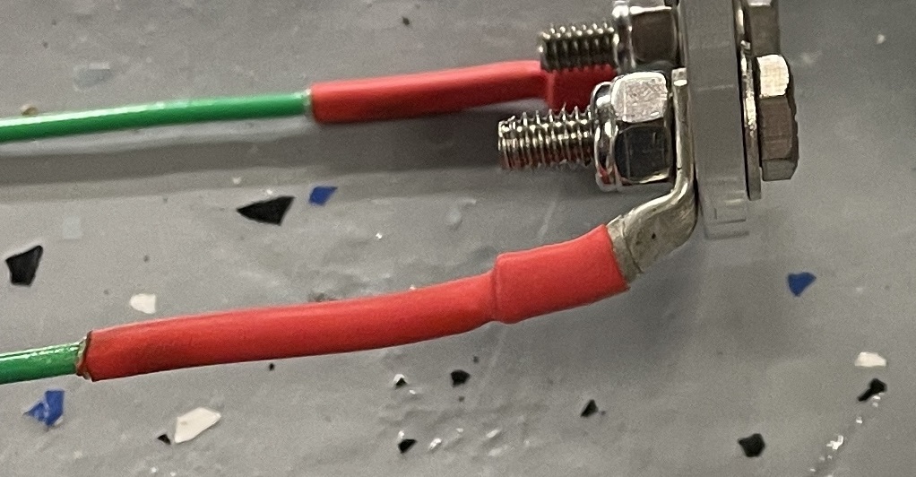
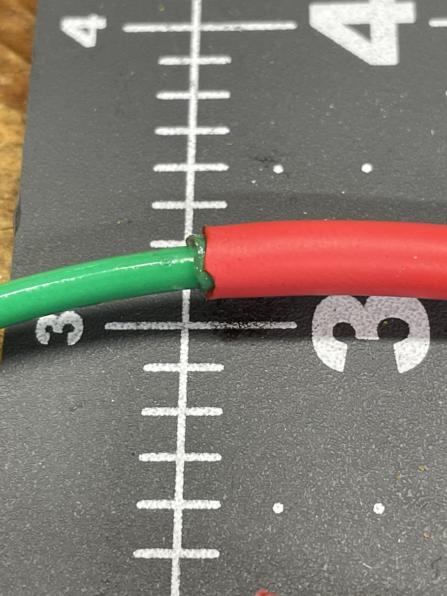
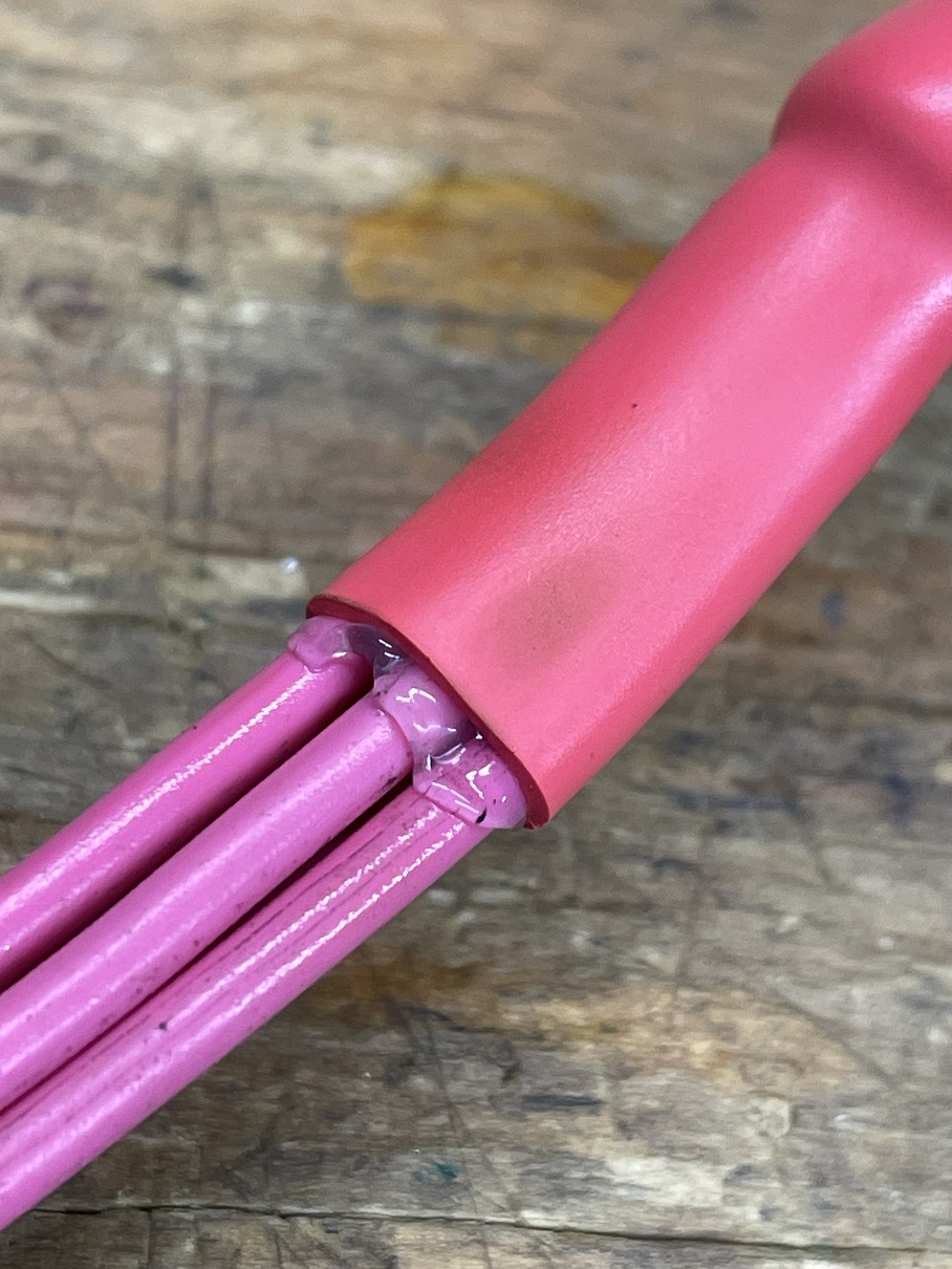
I also bought a kit of glue filled waterproof heat shrink off amazon. I used a heat gun to shrink it down but a small lighter or torch work as well. The glue will ooze right out the end sealing it against water. Really great heat shrink! Use stainless steel bolts and nylon lock nuts on everything. Corrosion is the enemy so use nothing that can rust.
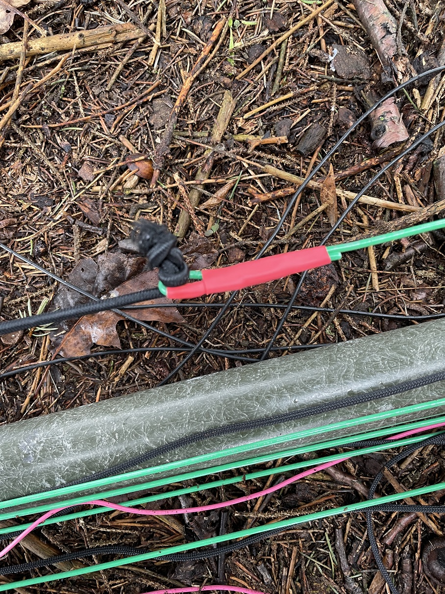
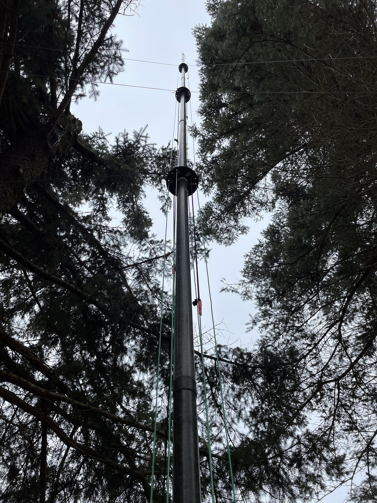
Assembly of the main feed wires: I ended up using 36ft (9 sections) of these military poles. This allowed me to use a full length 1/4 wave on all bands (including 40m) without any of the long fold overs used on the DX Commander. I also used 3 spacers (1 every 2 sections starting at #3 pole) to spread the antenna radiator lines and guyed them with guy rope. This antenna is HEAVY since it uses the thick fiberglass poles. It absolutely has to by secured every 2 sections with guy rope. No problem! The antenna feed wires are secured using 4mm Dyneema shock cord to keep them tight. I did not use any carabiner hooks and instead used a “stopper Knot”. Simple and there are tons of YouTube videos on this knot.
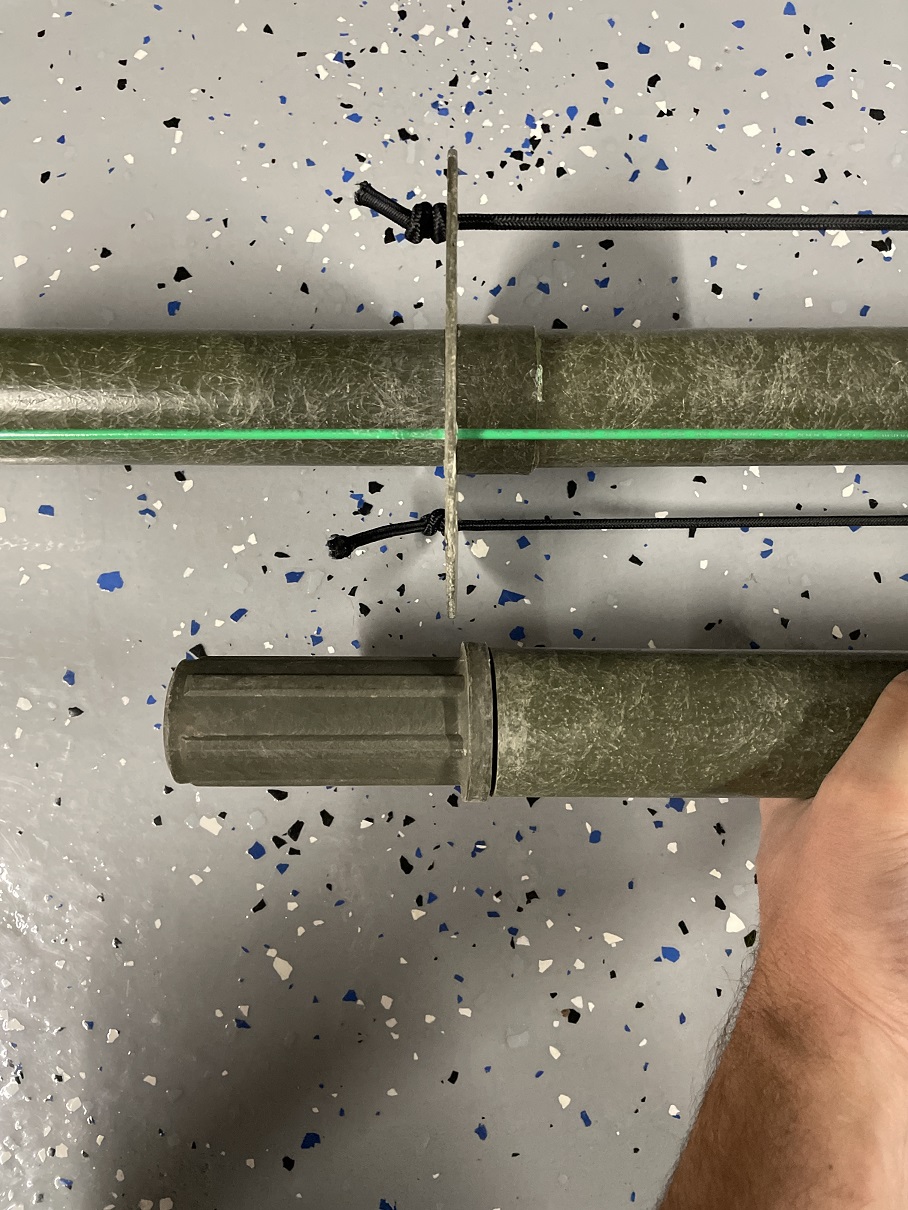
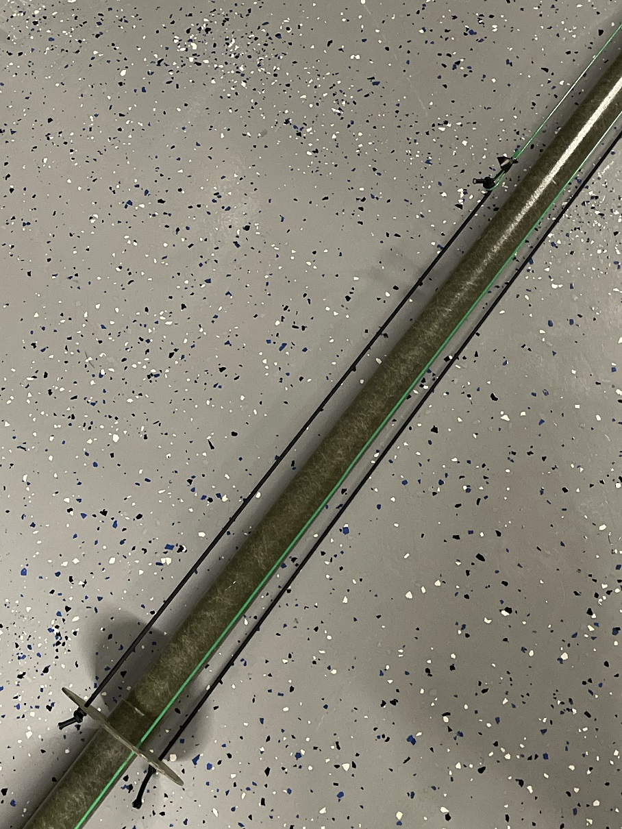
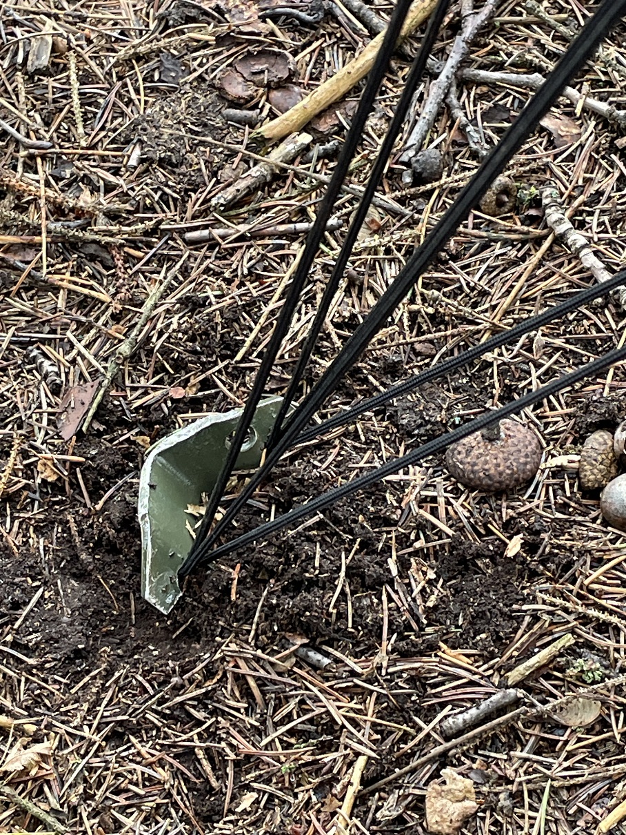
My spacers just get sandwiched between the poles. Nothing needed other than gravity and shock cord resistance to hold this entire antenna together. For the lengths of the 6 radiators, its best to start slightly long. Its easy to trim them if needed but if you need them longer, it requires soldering short extensions. I had to do this on 4 of my 6 feed lines and its not fun but its not too difficult.
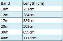
Final lengths for my 6 radiator wires. (15m is shared with 40m)
SWR chart after tuning. I targeted the CW & Digital portions of the bands.
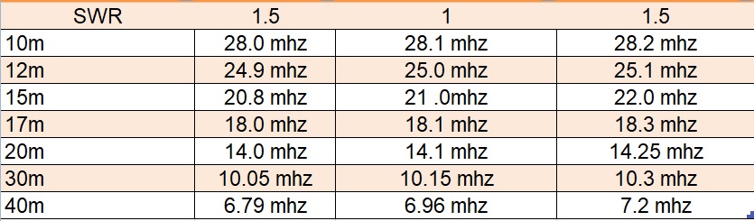
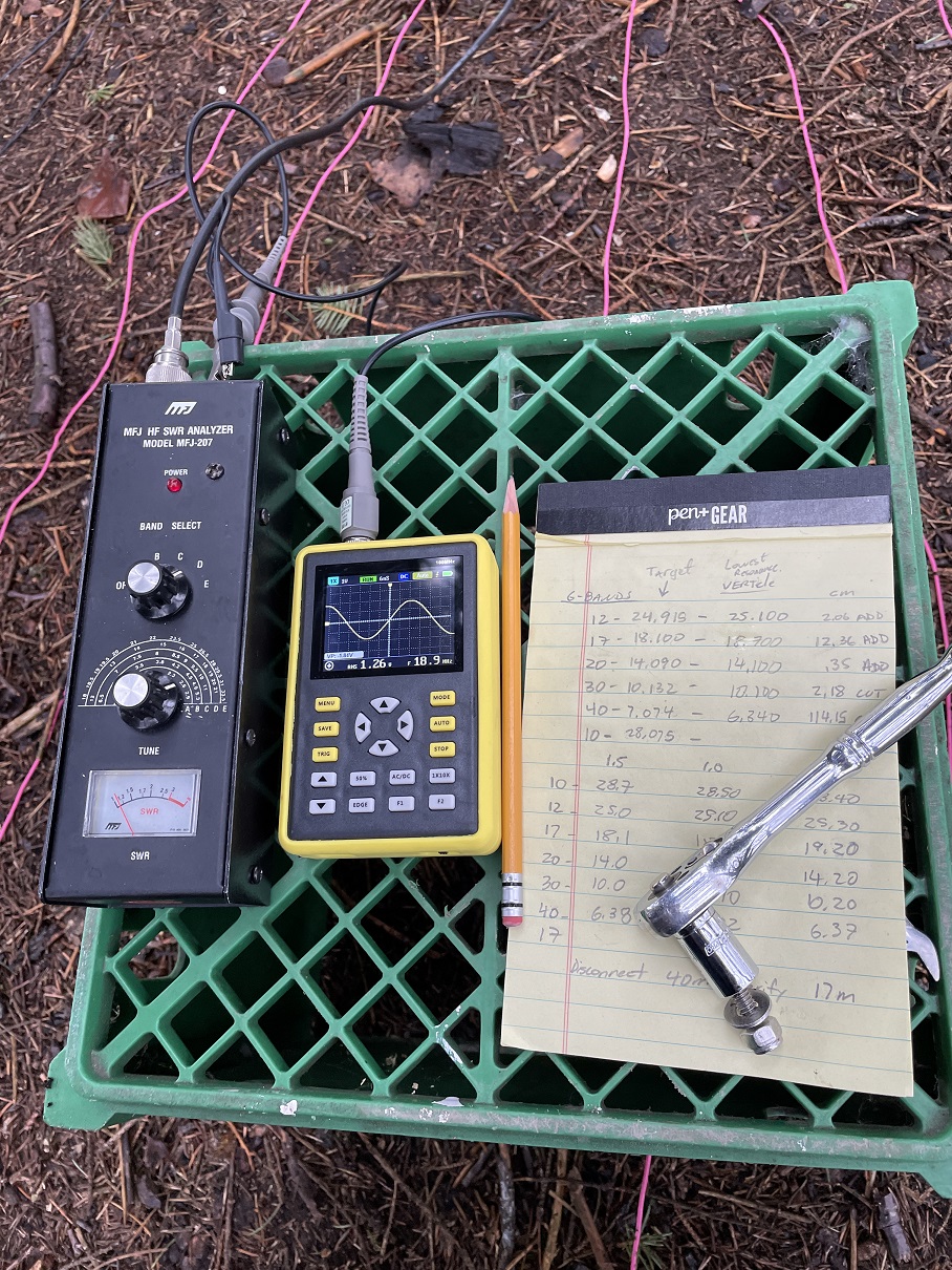
Tuning: I tuned my antenna exactly per the DX Commander instructions. I have about 5cm of fold over on every feed line to hold onto the stop knots. I used Callums SWR calculator which worked perfectly to cut or lengthen my radiators. I used a simple MFJ antenna analyzer along with a portable oscilloscope to read the frequencies. I highly recommend you measure each band at 1.5 , 1 and then again at 1.5 SWR. This gives you a good idea of your antennas SWR range. When you cut your antenna (or lengthen) you must maintain the original fold over length (5cm in my case). The antenna SWR will adjust exactly like the calculator predicts.
I used 3/32 Dacron rope for the guys and heavy 2ft long aluminum tent stakes that I bought from army surplus store. I used a knot called the “Taut-line Hitch” which is a really cool knot used for setting up tents. It’s so effective that it will pull the antenna down or pull the stakes out if you slide it too tight. The guy lines don’t need to be so tight that you can “twang” them like a guitar. They should have some room to move. 3 guys on every spacer will really hold the antenna well.
All ground mount antennas need a good ground plane. I used 36 radials around 3 to 3.5m long each. There are tons of YouTube videos on ground radials and how these work. Callum also has some great videos on them. Mine curve around trees and are not perfectly arrayed in a equal pattern. It does not seem to matter much as long as you get them down there. Mine are in bunches of 5 per lug (some are 6 per lug). I used odd wire I had laying around and the gauge of the wire is not important. The gauge must be strong enough not to break is the only requirement. No need for expensive heavy gauge wire on the ground plane. I used 16 and 18 gauge wire.
That’s pretty much it for this build. Some other information about the antenna – I feed it with 175ft of Davis RF Bury Flex Coax. The antenna is in the middle of some trees (so I don’t have to mow around the guy ropes). I have read a lot about trees and HF ground mounts. The trees can have some affect on the antenna depending on how much water is in the trunk however I don’t really notice anything. I have seen YouTube videos of people installing DX Commanders in the middle of a forest with no issues. Performance has been outstanding so far and requires no tuner. This ground mount Vertical antenna does not work on 80m but my doublet works well on 80m. It is possible to add 80m to this antenna however with the 80m doublet, I did not need to add it.
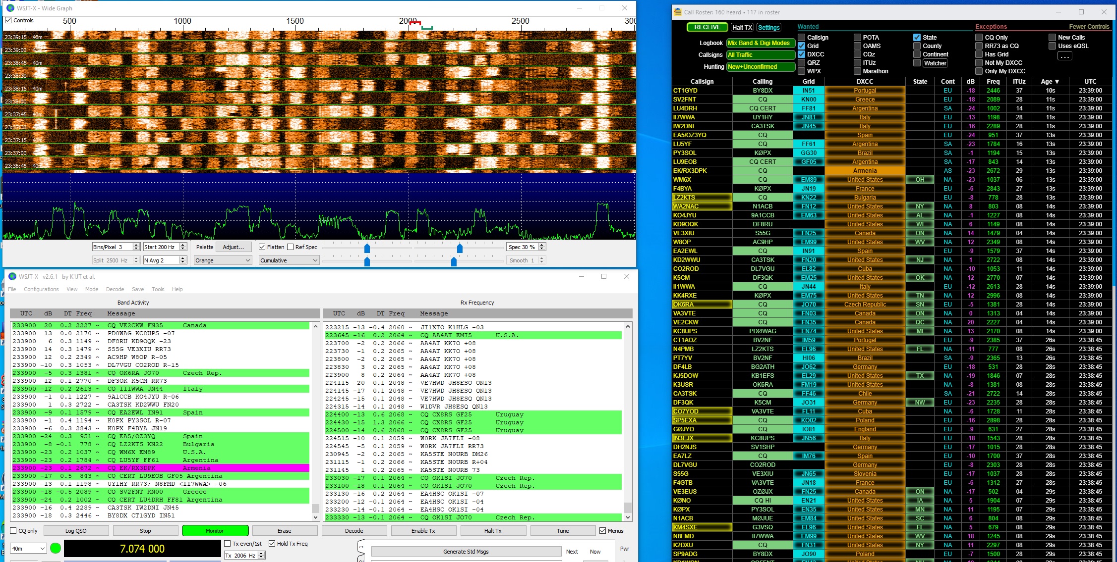
FT8 shown above with a lot of signals. No tuner is a great feature of this Antenna. I highly recommend building one.
Mike Freeman – KC8QNO
Hello I also started to reproduce a vertical antenna according to your sketches. I don’t know if you measured the capacitance between the counterweight plate and the radial plate? I measured this capacity (No wires mounted) and I found 17 Pf. I don’t know if this capacity is high or small. The insulator I used is about 3 cm. Translation with google.
I have not measured capacitance. Next time I have my meter out I will do it.
I used to have a similar ant which works well, but since I’ve made resonant elevated verticals, and got 2 S points gain, and lots more dx, over 10,000 miles everyday.
Hi Mike this is Mark Jaruzel (KE8BYG) back from the days of Otisville.
I have been staying in contact with your brother, Brian, for some time. I’m reaching out to you because I am going through boxes of “stuff” that have accumulated over the years. As it turns out there are several boxes of semicounductor data books that are looking for a good home. Judging from your web site, you might appreciate such items?:)
Feel free to shoot a text or call (810.348.6212) should you be interested.
I pray you and your family are doing well.
May God bless you,
Mark
Wow, if he’s not interested, I am. God bless, brother.
w8bis