
The Tachometer
The tach will measure RPM of an R/C helicopter rotor using a shutter effect by rotating a disc at a known RPM and displaying the result on a LCD screen. The user looks through a “view hole” and attempts to stop the blades with the shutter speed control. When the disc RPM matches the rotor RPM, the rotor will look like its not rotating. It’s a very simple concept and works very well for this application. The memory button when pressed will take a “snap shot” of the RPM at that moment and display it on the screen.
This project requires some fairly good soldering skills and some fabrication ability is helpful. I have a full workshop with a mill, lathe, drill press, and other tools which greatly helped. If you do not have access to a workshop, you will have to make due with a hand drill and a dremel or whatever you happen to have. I will try to keep this simple but yet give enough info so you can understand what is going on. I advise that you read the entire document before starting.You can get some tips and ideas from several others that also built this tach. I posted this project at www.helifreak.com in the tech room.
Here is a direct link: Finless Bob’s Helifreak Tech Room for added support. Also feel free to email me if you have any troubles.
Tools Needed:
- 20 Watt Soldering Iron / Pin
- Wire Cutters
- Rosin Core Solder (smallest diameter you can find)
- Small hobby saw
- Screw Drivers (Phillips & Straight)
- Drill
- Dremel (or your neighbors workshop)
- Multi-Meter
- CA or Epoxy
- PIC Chip Programmer (more on this later)
- Black electric tape
18 pin chip socket Socket for PIC 16F628A Optional and not req’d.
All of these parts can be purchased at www.futurlec.com ,www.mouser.com, or www.digikey.com. I personally like Futurlec because they have the hobbyist in mind and their site is very easy to find items but their shipping is slow. You can buy them from anywhere you feel comfortable. You are welcome to substitute items such as the IR sensors and LED’s for other brands or types. Anything will work as long as it can see the rotating disc. A hall effect sensor could easily be used just like the heli hall effect sensors on the governor. Buttons and switches are not critical and anything will work. The critical items: PIC16F628A, LM7805, 317T, the HD44780 LCD screen, and the resistor values. My schematics are based on those items and if you swap them out you may have to alter other parts and the software code.
Parts List: Description Comment
LM7805 5v voltage regulator T0-220 size
10uF cap Electrolytic capacitor Any voltage rating will work
QSE114 Phototransistor (IR)
4.7K ohm (two) 1/8 watt resistor
1.7V IR LED Infrared LED
317T Variable voltage regulator
10K Trimpot 10K ohm potentiometer
1N4002 Diode
2.5K pot 2.5K ohm Precision Pot.
16×2 LCD HD44780 Controller type
PIC 16F628A 18 pin Pic Micro Chip
Switch Power switch can be any type of switch
Push Button Micro Push Button can use any type
Knob Knob for 2.5K Pot.
Wire Misc. small wire
Project Box 102 x 68 x 37 mm
Experimenters Board 120 x 80 mm.
150 ohm 1/8 watt resistor
Motor Small dc motor kids toy? servo?
9v Battery Battery
Scrap Balsa or plastic
Assembly:
Step 1
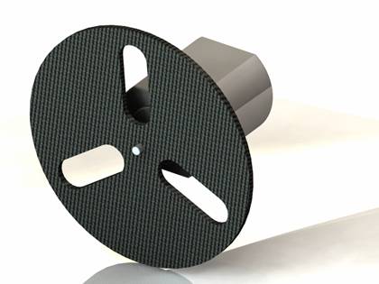
You need to make the rotating shutter disc. Mine is about 2” in diameter and has three equally spaced slots cut into it. The diameter can be changed to suit your box size but it must have 3 slots as shown and keep the slot width 0.250” or less. It needs to be thick enough to withstand 300-1000 RPM. Mine is 0.050” thick or so and is made out of carbon fiber. You can make the disc out of anything such as balsa, plastic, thin plywood, or metal. My first disc was balsa and worked quite well. The center hole needs to fit tightly on the servo motor shaft in which you will glue it with epoxy or CA.
Step 2
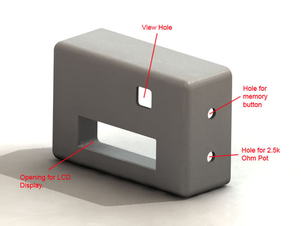
The project box needs a few cut-outs and holes. The location of the holes is not critical and should suit your needs. I was able to fit everything in my plastic box with the holes located in the diagram below. You need to place the motor and shutter disc assembly from Step 1 into the box to get a rough idea where the view hole needs to go. The same applies for the LCD screen, memory button, and the 2.5k pot. They all need to fit in the box without rubbing the shutter disc. This was tricky but can be done. The slots on the shutter disc must pass in front of the view hole for this to work. You should be able to see through the disc when it’s spinning. The LCD screen should fit into the opening with no resistance. Do not force the screen because it’s extremely fragile. I broke one already trying to force it into a smaller hole. There are two more small holes not shown and they are for the 10k trim pot and the power switch. These can go anywhere you choose and mine are on the bottom side.
I glued the motor to a piece scrap balsa to hold it in its final spot. Do not glue anything until you are certain of its location. As a reference you can see how I fit everything in there from the picture below. It’s a tight fit and might take some adjusting but you can get it all in there with room to spare. The image below is the project box with the back cover removed so you can see where everything fits.
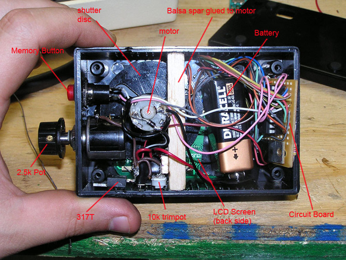
You can not see them but the IR LED and the QSE114 sensor are under the balsa spar. The computer (PIC 16F628A) has to be able to “see” the spinning shutter disc. To accomplish this we use an Infrared beam of light. The IR LED will not be visible to the human eye so it’s hard to tell if it’s working. I used a multi-meter set on milli-amps and measured a few milli-amps in the circuit to see if it was working. If it’s off you will get zero. The IR LED needs to shine through the disc slots and the QSE114 sensor needs to be mounted on the opposite side of the disc to “see” the Infrared beam (see diagram below). This works exactly like those garage door opener sensors that are mounted by the floor on your garage door. If you get in the way of the garage door sensor beam, the door stops going down. In our case with the tach, the slots in the spinning disc will repeatedly break the infrared beam allowing the computer to “read” the pulses from the sensor. The computer simply counts the pulses for a given time span and knows exactly the RPM of the disc.
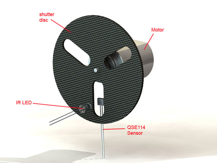
IR LED and Sensor setup for the shutter disc
Step 3
The electrical side of this project is the more difficult part. I drew up some schematics and tried to simplify it the best I could. Take your time and check your work and you will be fine. I recommend building this in some sort of breadboard and get it working first. Afterwards, go ahead and solder everything in place. This is of course optional and not required, but it saved me some headaches.
The easiest way to build this is to break up the circuit into 4 smaller circuits. These 4 circuits connect together to make the final bigger circuit. It is much easier to work on one part at a time and get it working 100% before moving on to the next one.
The Motor Circuit: This is the motor circuit. The 2.5K pot will be your fine tune adjustment knob for the shutter speed. The 10k trim pot will set your max RPM level. Once it’s set to your liking, the 2.5K Pot will fine tune the RPM from 900RPM to the MAX level you set. There is no need to solder this on a circuit board. I just glued the 317T to the side of the box. The battery connects to the input. Note: You will only use two of the pins on the pots (they have three pins).
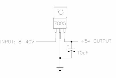
The Power Supply Circuit: This circuit will provide 5 Volts to all the digital parts and LCD screen. The 10uF cap functions as a simple noise filter. The battery connects to the input.
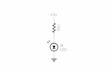
The Infrared LED Circuit: Very simple circuit for the IR LED. The 150 Ohm resistor will limit the amperage that the LED will use and keep it from burning out. Note: Ohm’s Law V=IR if you are interested. This circuit gets +5V from the power supply you built earlier and draws 33 mA
The LCD & RPM counter: This is the most complicated part. There are only 7 parts but there are a lot of wires. Don’t panic, it’s not as bad as it looks. If you happen to wire it up wrong it will not damage anything. I even wired mine wrong the first time so just take it slow and check your work. This circuit also gets +5V from the power supply you built. The PIC 16F628A needs to be programmed for this to work as well (explained later on in Step 4).
That is all for the electrical assembly. The only thing connecting these 4 circuits together is the power. I wired a switch in the battery leads to turn the tach on and off. I put the “power supply” circuit and the “LCD and RPM counter” circuit on the same circuit board. It is possible to solder the 16F684A direct to the circuit board but you MUST have it successfully programmed before you do so. I always use an 18pin socket so I can remove it if I need to.

If you are wondering where I got all the small colorful wire, I will tell you a secret to a nice supply of small wire. Find an old computer serial cable or parallel port printer cable that is no longer used. I buy these from garage sales all the time for cheap. Cut the ends off and strip the outer cable off. There are at least 25 different color wires in there that are 6ft long and very flexible. CAT5e cable is absolutely terrible to mess with and it is really stiff. I do not recommend using that.

Wire from an old Parallel Port cable.
Step 4
Programming the PIC16F628A
Programming the PIC16F628A is very simple however you need a device called a “PIC Programmer” to do it. It’s a small interface that will connect to your computer’s serial or parallel port. The PIC chip plugs into the programmer and you load the software (HEX file) into it from the computer. The manual for the programmer will tell you how to accomplish this.
Files needed:
Hex File – TACH.HEX (right click and save as)
If you want the source code it is posted at the bottom of the web site.

Example Pic Programmer
A PIC programmer cost about $25-$30. They come as a kit that you have to build. Some of them are already assembled but those cost more ($50+). Mine is called a PICALL programmer and it was $20 about 10 yrs ago www.picallw.com. It took me 2hrs to build and the instructions were very easy to follow. I am not sure if it’s still available but you can use any programmer that supports the PIC chips. I have even seen them for sale on www.amazon.com. Just do a google search for a “PIC Programmer” and you will get a lot of results. I also see quite a few on EBAY that are low cost.
If you can not program your PIC, send me an email. I will gladly program anyone’s chip for free. All I ask is that you pay for shipping both ways.
I included the HEX file which is the software that you need to write to the PIC16F628A chip for the tach to work properly. When you buy a PIC programmer, it will write the HEX file to the chip for you. I also included the source code in case anyone wants to modify the software to suit their needs. I am not going to go into detail on how to code software for the PIC chip. There are many books and web sites that have information about how that works. The “assembly” language that the PIC chips reads is a “low level” language and is difficult to learn. I highly recommend using software like PICBASIC that will allow you to write code in BASIC, which is high level and very easy to learn. The PICBASIC software will “cross compile” your BASIC code into assembly and it will make the HEX file for you. It’s much easier and is quite powerful.
The software I wrote for the tachometer is simple and functions as follows:
The screen updates the RPM every 1.5 seconds since that’s how long it reads the sensor. The longer you read the sensor, the more accurate the RPM is. There is a trade off due to the math in step 3. If you read the sensor longer, the resolution goes higher however the screen update gets longer which can be a pain. If you read the sensor shorter for example perhaps it’s only .5 seconds, then you get a fast screen update but the RPM is low resolution which causes the RPM to count by 50’s. I tried to get the best of both worlds. Reading the sensor for 1.5 seconds, the RPM will count by 20’s which is pretty good. It’s stable and does not jump all over the place. The reason I used three slots instead of one was to slow down the “real” RPM of the wheel. I tried it with one slot and the wheel had to physically spin at 3000 RPM to read a 3000RPM heli rotor. This made the tach vibrate and it was very noisy. Three slots caused the wheel to spin at 1/3rd of its original speed and it was very quiet. When the tach is reading a rotor RPM of 3000, the wheel inside the tach is actually spinning at 1000RPM.
I gave my homemade tach to a buddy that flies all the time and he seems to like it. He has told me that its accuracy is perfect so far and it easily can read RPM up to around 6000. I included some additional pictures of the inside of the tach in case anyone is having trouble fitting everything inside.
Step 1 – The computer initializes and displays the welcome screen.
Step 2 – The computer will read the sensor for 1.5 seconds and count how many times the slot goes by.
Step 3 – There are three slots on the wheel. The computer has to do some simple math to convert the number from step 2 to RPM. It will divide the result by 3 and convert 1.5 seconds to minutes to get RPM.
Step 4 – The result from step 3 gets sent to the LCD screen for you to see.
Step 5 – Repeat Go to Step 2


Several assembly tips:
- Too much heat from the solder iron is bad. 15-20 Watts is plenty for this project. When soldering the PIC chip, be quick about it and do not let the chip heat up too much or you may damage it. I recommend using an 18pin socket so you can avoid soldering the PIC at all.
- Too much solder is also bad. Have a solder sucker nearby if you use too much.
- Pre “tin” the wire ends with solder. This helps tremendously when soldering wires together.
- When you finish the shutter wheel, try it out on the motor before you glue it. Make sure it’s on the shaft straight with no wobble. (hook up a battery to the motor to test it out)
- Measure your LCD screen and make sure it easily fits in the hole you made in the project box. It does not need to fit tightly and you will epoxy it in place when finished.
- Optional: Use a breadboard to assemble the circuits first. It’s an easy way to build the circuit without using any solder. Breadboards are cheap and are a very good tool to have on the workbench bench.
- Buy extra parts (resistors, diodes, etc). You might accidentally destroy something or lose it. These parts are cheap and it will save some of your sanity.
- Don’t use anything too shiny for the shutter disc. I have had reports that the sensor has trouble “seeing” the IR LED if the disc is too shiny.
If you need help email me but please do not ask me to build one of these for you. I only posted this information to provide you with a fun way to make your own heli tachometer.
Source Code for the PIC Chip (right click and save as):
Tach.bas – This is the PIC BASIC Source code.
Tach.asm – This is the Assembly Source Code.
Looks great. I’m off to start collecting some bits…
I’m bookmarking your site for future reference.
Keep up the good work.
david
Hey Mike…I’ve been looking at this project for a while and I am about to start working on one. I have a question…Looking at your LM317…it looks as though it is wired in backwards. If I’m not mistaken, the left most pin is the input, the middle pin is the adjust, and the right pin is the output. I’ve never used one to power a motor before, so I may be thinking incorrectly. I also have an idea for a couple of changes in the project…I’d like to run them by you in an e-mail…
Thanks
Oh, by the way, your condor ar-15 adapter looks like WOK’s !! Nice job…he sells his, you ought to think about selling your design on here 😀
I did not think it was backwards?? I know a bunch of people that have built this and had no problems.
I am open to any ideas. Lots of people have changed little things here and there to make it better. one guy put a voltage readout on the screen which was cool.
WOK’s guard is what inspired mine. I just made mine curved with the CNC.
Indeed, the TO-220 package LM317 variable positive regulator, at least from the manufacturer’s data sheets, has input on pin 1- leftmost and the output on pin 3. I assume the intent was to provide a variable DC voltage to the motor. However that is a minor typo on an otherwise clever bit of engineering. My problem is getting the BAS source code to compile as I want to try a slightly different application and need to make it straight RPM not divide by 3. Thanks for taking the time and effort to make this available.
its counting its own rpm. What a useless device is that?
Dear Mike will you send my the Hex file of you tachometer. I can not download from the net.
Bob from the Netherlands.