
I have wanted to make my own clock for a while now. There are many books with plans and methods to do this and they all have some great information. I decided to read a book written by W.R. Smith called “Skeleton Wall Clock”. He does an excellent job explaining the function of every part of the clock and how to make it. His clock design is the basis of my clock and will run for 8 days before it needs to be wound. There are of course many alternate ways of making the parts and I plan on using what I have in my shop.
The first thing I did was draw the complete clock in 3D with Solidworks. This helped me see exactly how the clock works (I also now have every part drawn). W.R. Smith used all the traditional tools to make the clock in his book. He had a Myford Lathe, drill press, bandsaw, and other tools. He did not use a mill whatsoever. I however own a CNC mill and plan on using it to cut out most of the parts. I also own a lathe which is required to make many parts. His book has no information about CNC so I had to do all that myself. I also changed the design of the clock quite a bit to fit the limits of my mill. The clock shown above does not look like the original clock in W.R. Smiths book. I also changed materials quite a bit. I used what I had around in my shop which should work just fine. W.R. Smith calls for a lot of brass which is very expensive. I plan on using brass for the gear train but I also used a lot of aluminum and G10 for the frames.

I cut the frames out of 1/8 inch black G10. It is very strong and cheap. I recommend cutting it out with carbide tools since its very abrasive.

The frame standoffs are brass and made on the lathe. I changed the clock design so I only needed 3 of these instead of 4.


This is the ratchet wheel (above). It is part of the drum assembly. The drum assembly with the great wheel is one of the most complicated parts of the clock.

Cutting out the great wheel was a huge project. I had to cut it out with a 1/16 end mill. I wanted to have a 0.250 thick great wheel but that was just not going to happen with a 1/16 cutter. I broke 3 of them when I got 1/8 inch deep so I quit and fly cut the gear to 1/8 inch thick. I guess I will have to live with a thinner great wheel.

Cutting the drum assembly shaft

This is the main shaft for the drum assembly / great wheel. It is made out of steel. It will hold the 7 lb clock weight and will power the entire clock train.

Here are all the parts of the drum assembly. The drum, shaft, ratchet wheel, click, and the click spring. I cut all these parts out on the CNC mill except for the main shaft and the drum. The drum end caps were cut on the CNC.

This is what the lower clock looks like all assembled. Its starting to look like a clock now.
More to come.
Update 01-25-15
Finally dusted this thing off and started working on it today. Its been a few years but I just got too busy to work on it. I made a lantern pinion today. Man it took a few hours to make one but it turned out pretty good.
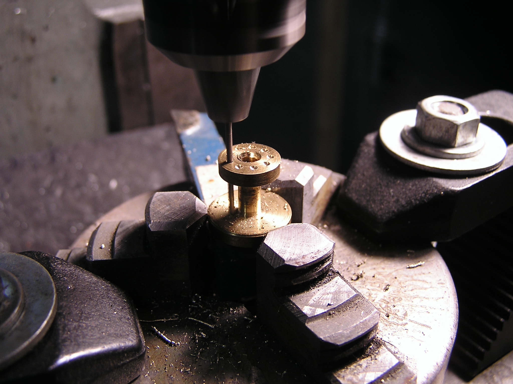
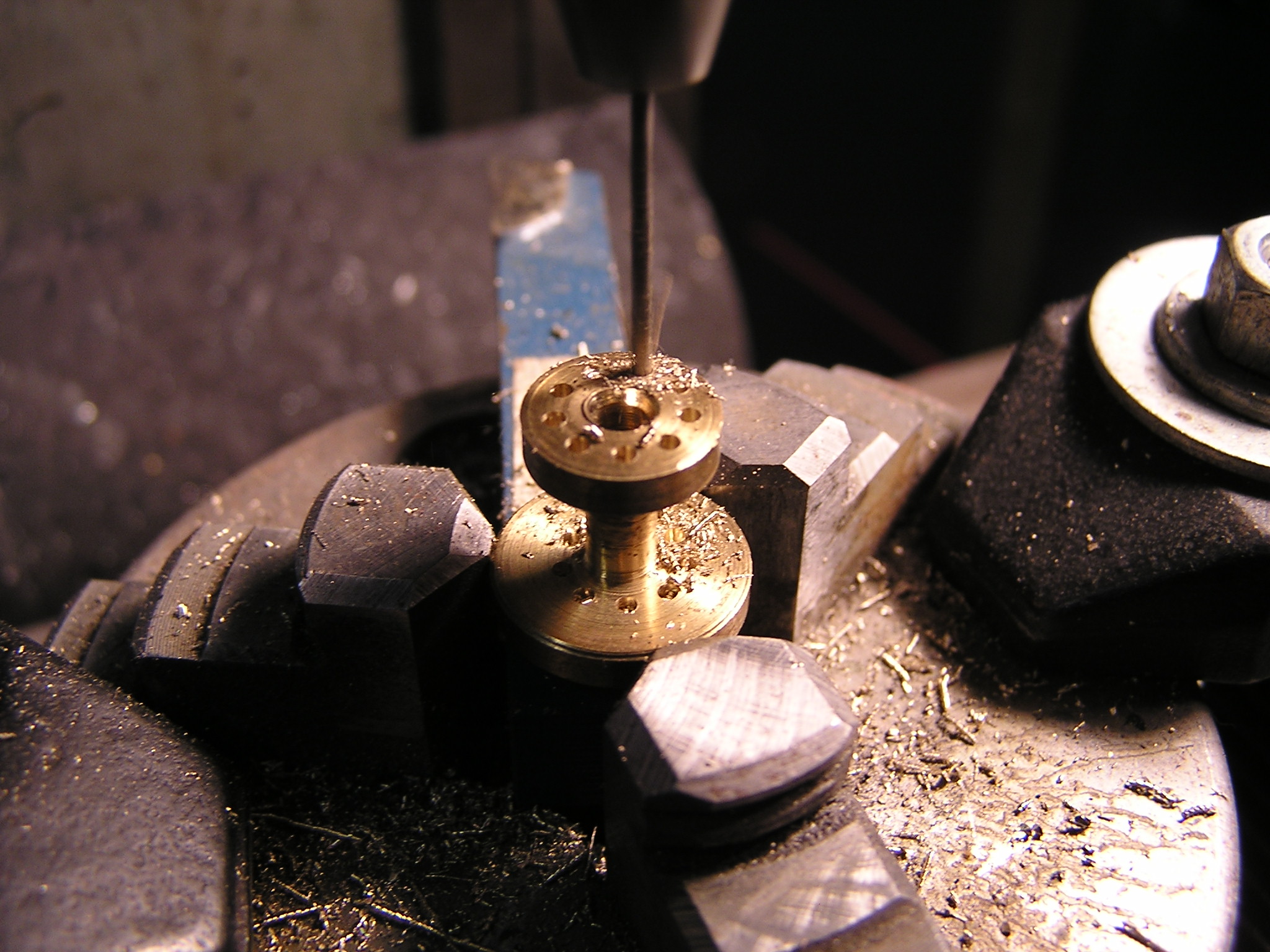
It’s made of brass and I cut it out on the lathe. You can see above I am drilling out the 9 holes for the pins on my CNC mill. I mounted it in a lathe chuck and clamped it to the mill table.
The pins are 0.048″ diameter made from music wire and 0.490″ long. The drill is a #56 (0.0465″) . Not a perfect match but close enough.
I had to make a 0.048″ reamer to get the pins to fit perfectly. I just made a reamer out of a piece of the music wire and ran the same CNC drill program again.
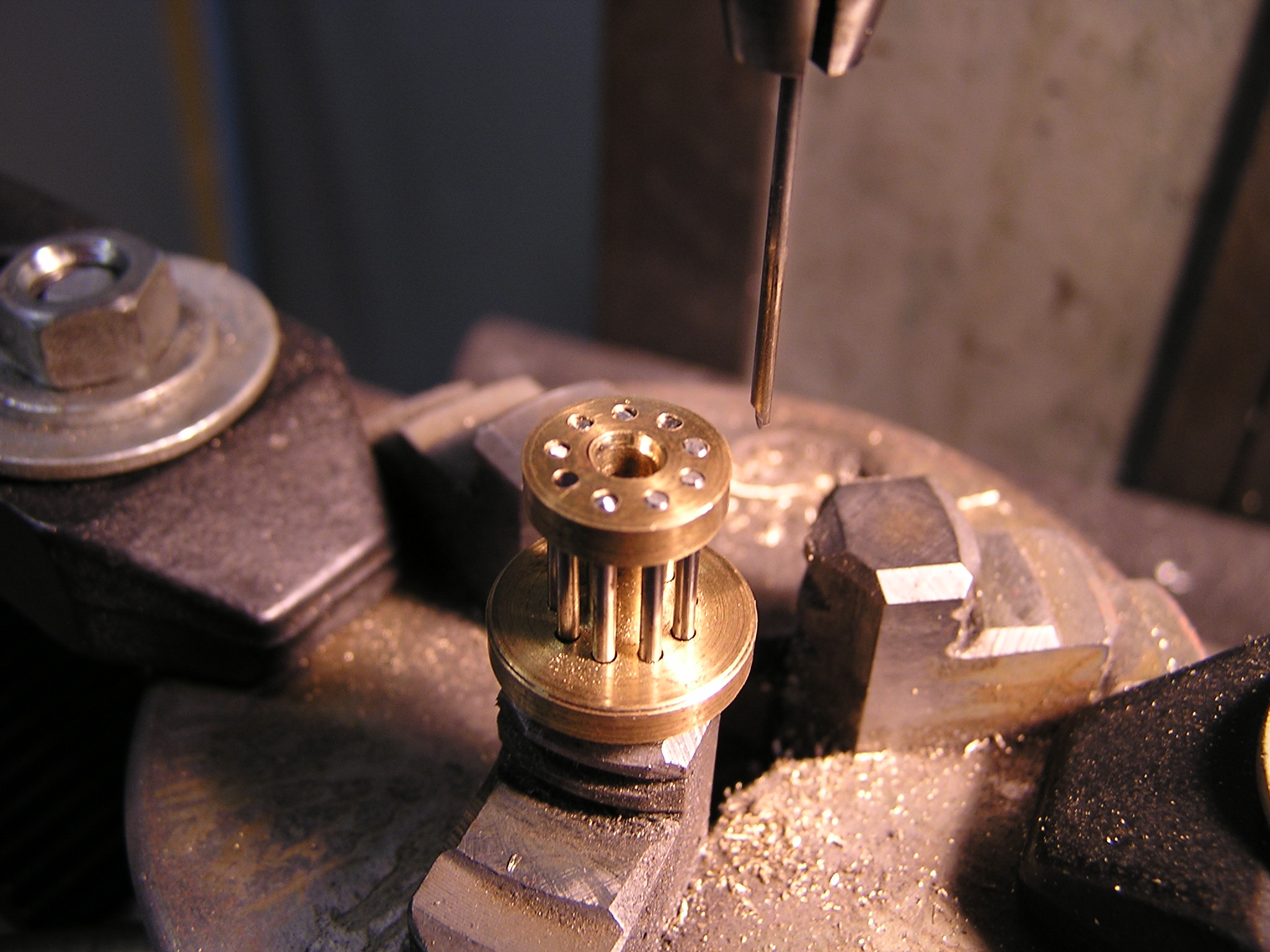
The pins fit perfect. Lantern pinion complete. I need 3 more but I might change the design to make them a bit more simple.
WOW!!! I repair clocks, and this clock is INCREDIBLE!!!
Any more updates??? 😀
I am going to finish the clock this winter. i do not have any more updates yet. sigh…..so busy these days.
Any chance of getting these cad files for download?
I love the Solid Works Drawings…Can I have them as well??
Great looking project would love a set of plans if you were willing to give them up.
Great project. Would love to see more of your process if you are willing to share?
Hi. Looks great. Any possibility of sending me a set of drawings? Any CAD file format should be OK.
is there maybe a posible way I can get your plans to build my own clock.
or somthing like the gear’s and there places ?
i am doeing this for a school project so my budget is very low
Is love to have a closer look at the solidworks part files… man does that ever look nice!