
Mechanical clocks are cool. I still see them around but mostly as decorative antiques on shelves and rarely working. The digital age has retired off many of them because of their superior accuracy and simplicity. No one wants to wind a clock anymore (except perhaps me…) . My grandfather collects antiques of all kinds and he bought this 1927 Ingraham mantle clock for $20 somewhere. He gave it to me non-working and challenged me to fix it. I knew nothing about clock repair when I took this home but thought it would be fun and I had nothing to lose. I figured dismantling this clock would give me some insight for the homemade skeleton clock that I want to build.

I started taking the clock apart and noticed right away that both main springs were broke and the entire clock mechanism was frozen. What a mess. I needed to order a new set of springs right away.
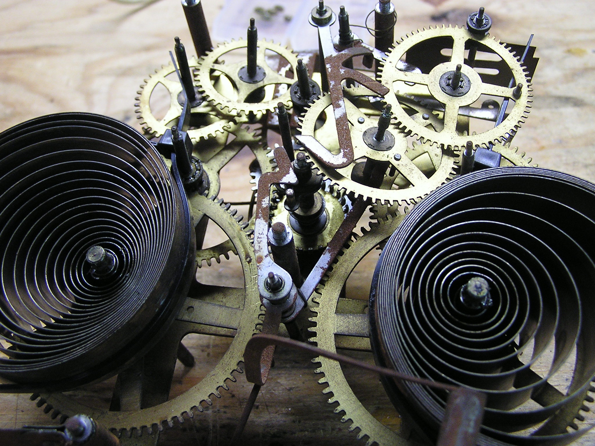
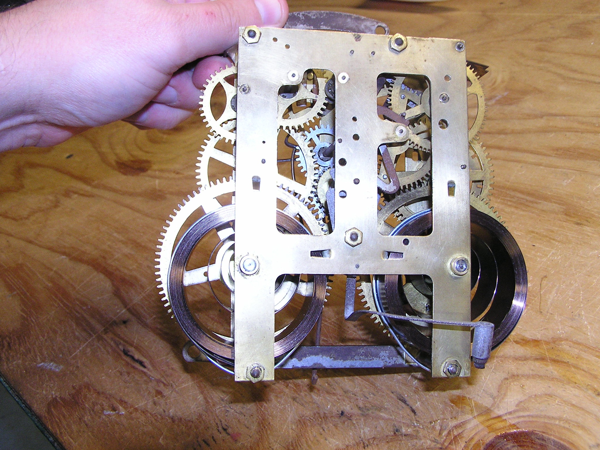
I removed one of the main plates that hold it together (see above). All the various gears are exposed and are removable now. There is old grease and dried oil everywhere. I made some sketches and took many pictures before I removed any gears. I was not sure how easy it would be for me to put this back together.
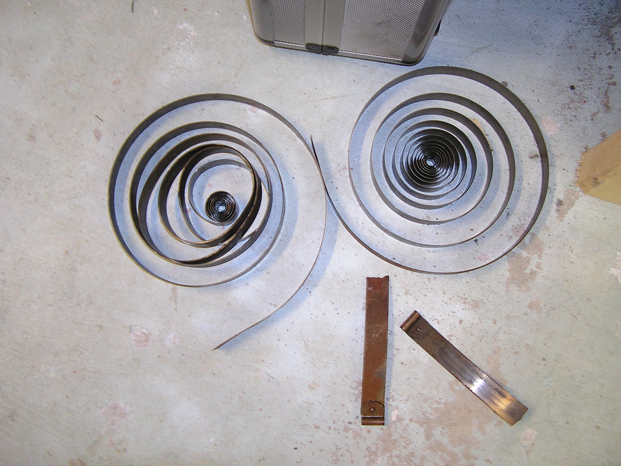
Broken Springs above have been removed.
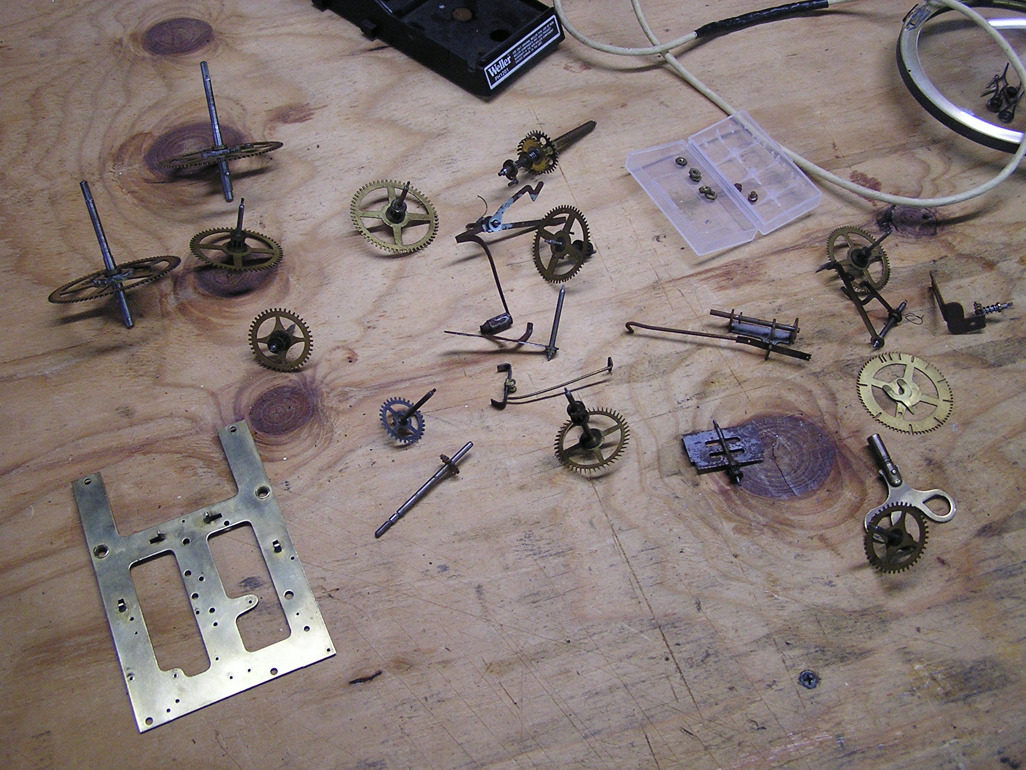
I cleaned all the gears and the back plates in carburetor cleaner and mineral spirits to dissolve the dried oil and grease. I am certain that is not the professional way to clean clock parts but it was what I had. If it can clean my engine parts it should work on the clock parts (and it did!).
At this point I stopped working on the clock and did a ton of reading on the internet. I needed to figure out what problems to look for on the clock movement so I could repair them. Cleaning the clock was the first step which I already did. The second step is to put it back together and look for worn “pivot” holes. Pivot holes are where the gear shafts rotate against the plates. There are no bearings in this clock. The gear shafts just run bare in the pivot holes with a light oil. Over time, this round holes start to wear out and become oval shaped. This causes the gear to shift out of alignment and if enough of the gears move out of alignment, the clock will stop.

My clock has a bunch of worn out pivots (see above, not my image). Fixing these requires “a bushing job”. I guess its pretty common for an old clock to need bushings. Simply drill out the old pivots with a drill and press in a new bushing that has a new small pivot hole. Easy for a clock repair shop that has the expensive bushing tool and every size bushing made. I do not have this luxury and I do not plan on buying any of their tools.
I do however own a lathe and a mill. I can make any size bushing I want on the lathe, and I can use the mill to drill out the old pivot.
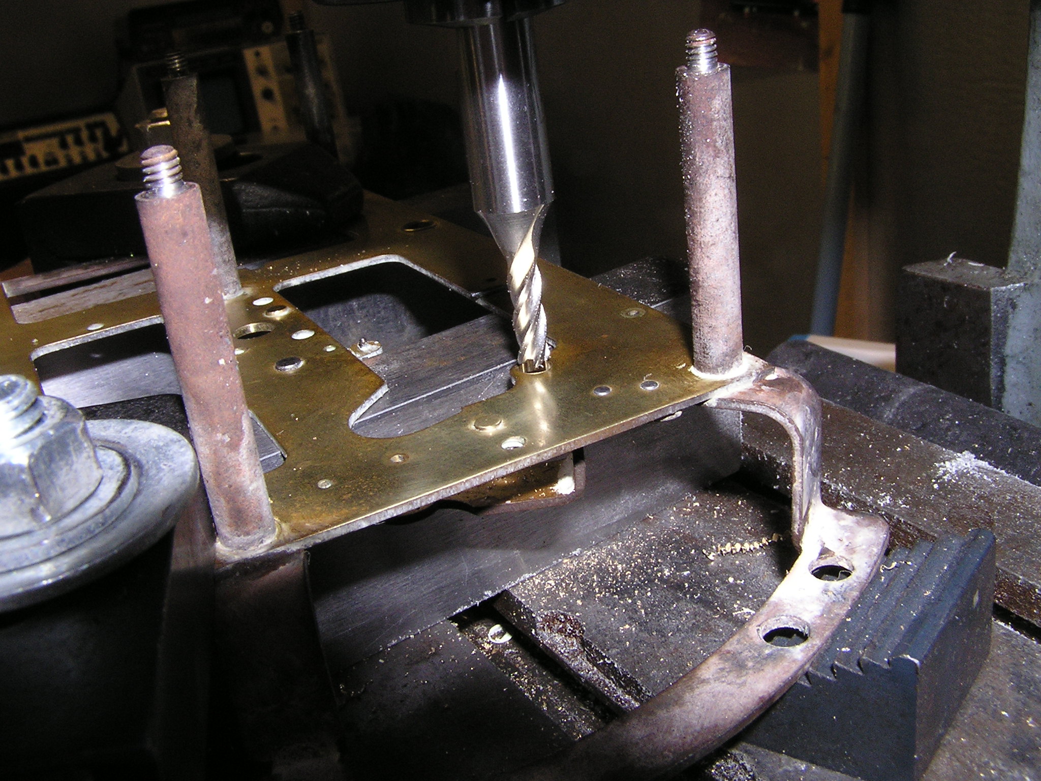
I marked all the bad pivot holes on a piece of paper and mounted the plate in the mill. I can’t just drill out the holes without thought. I need to find the exact center of the worn out hole. This is accomplished very easily but using a $5 tool called an edge finder. Every machinist has one of these in their box. One end of it will find the edge of a work piece and the other end is pointed and can be used to find the center of a hole. The pointed end will naturally find the real center of a worn hole. It worked perfect (see below).

After finding the center, I swapped out the edge finder with a 5/32 inch end mill and drilled out the old pivot hole. Drill bits wander in oval shaped holes so I decided to use the end mill. It worked well. Now onto the bushings.
Making bushings is easy. I have lots of 1/4″ brass rod so I got to work. Drill a small hole (smaller than the pivot shaft), machine the outer diameter to be 0.002-0.003 inch smaller than the newly made holes in the plate, then cut off the bushing to be 0.005-0.010 thicker than the plate.
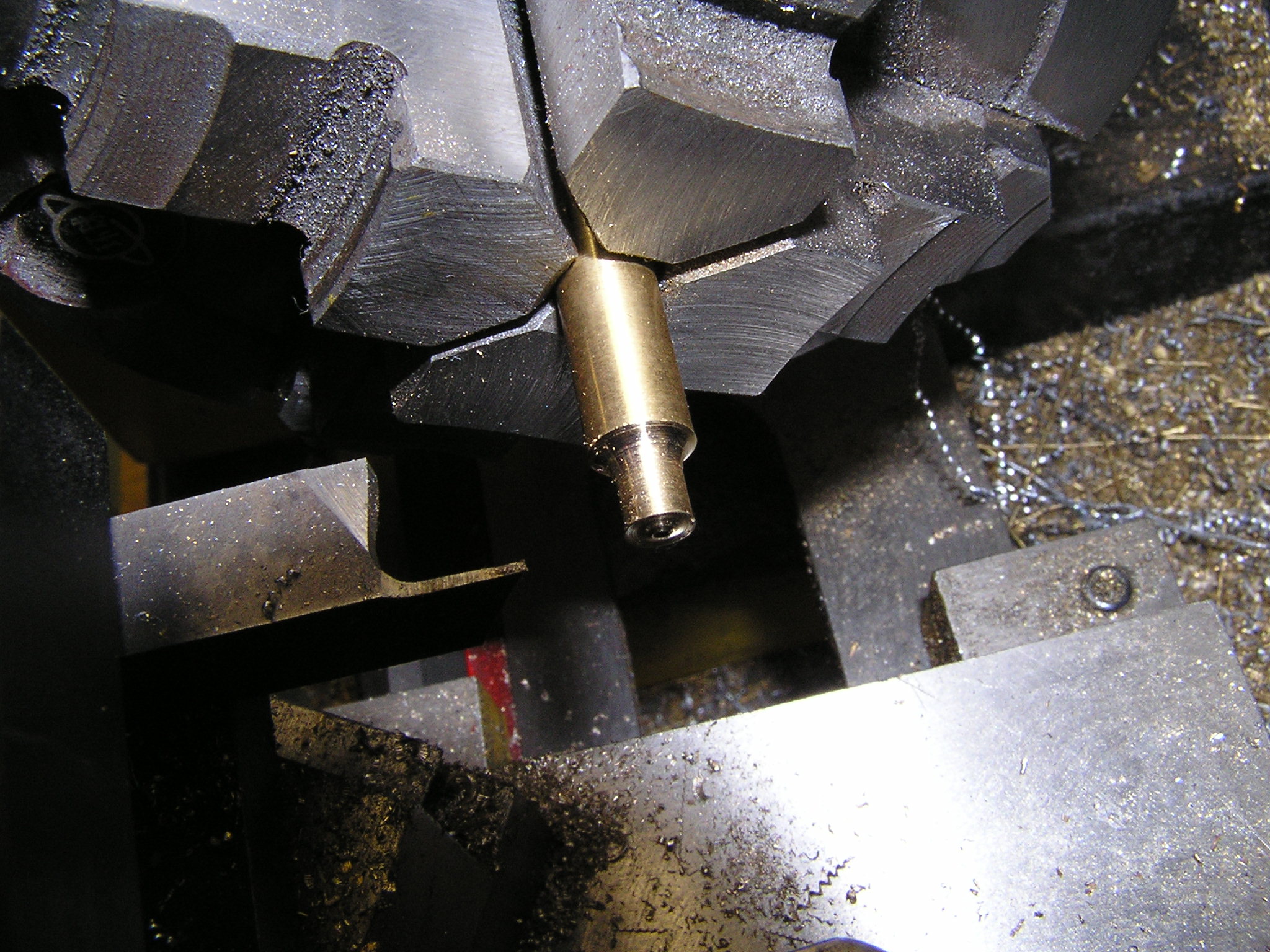
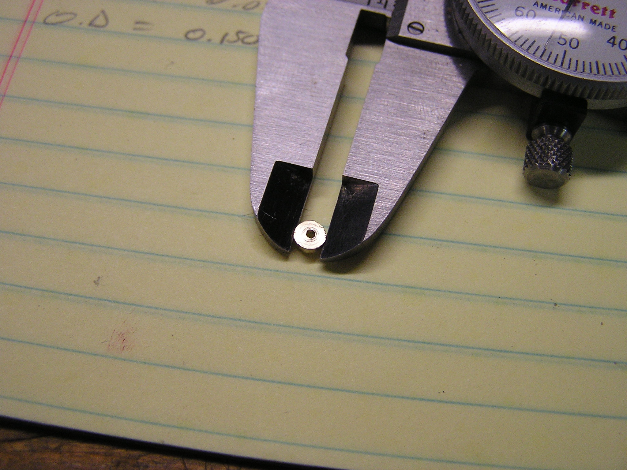
I drilled a 5/32 inch (0.156) hole and a 0.153 inch bushing should just fall into it. I then smash it good with a small ball peen hammer which will expand it to fit the hole tightly. It will also deform the inside pivot hole a little bit but that’s okay since it will get reamed out later.
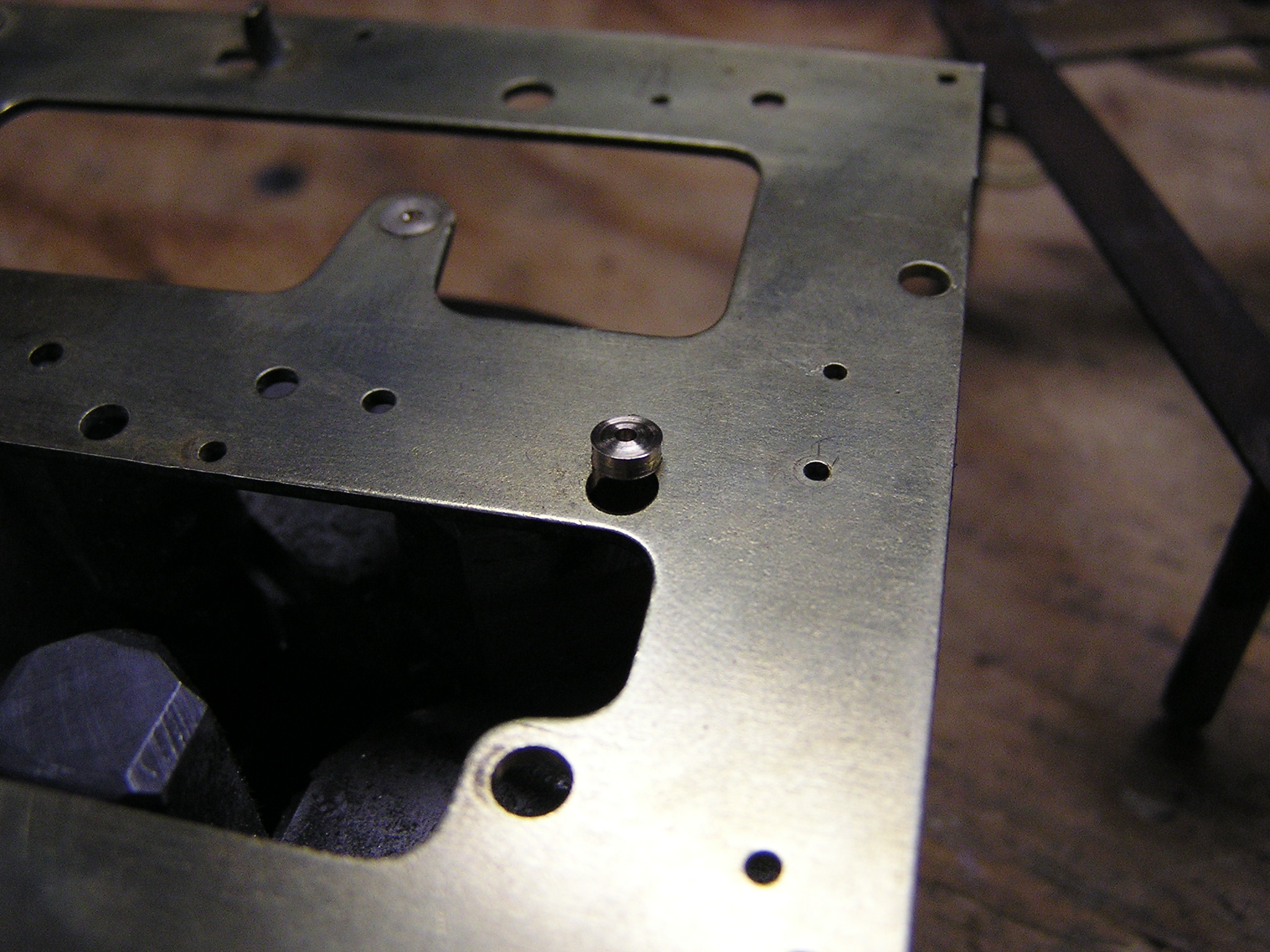
The bushings installed nicely. By now, my new main springs have arrived along with a few items and tools I needed for this project. In addition to the main springs, I ordered a set of 5 sided tapered reamers which I will use to size my new pivot holes, some synthetic clock oil, and several jewelers magnification loupes (2x, 4x, and 10x) so I can see what I am doing.
I purchased all my clock parts from www.timesavers.com They are located in Arizona USA.
Reaming the pivot holes is easy. Don’t go to crazy or else you will have to install a new bushing again. The holes are tapered and not straight like you might think (taper gets smaller going to the outside of the plate). From all my reading online about this, I have discovered that the tapered holes accomplish two things. First, it reduces friction on the pivot shaft so only the back part of the bushing will contact the pivot shaft. Second, it allows some gear “shake”. This is sideways movement that is allowable on the shaft. This will allow for slight mis alignment of the shaft when assembled and will prevent binding later on. I was pretty thankful for this feature since I had one hole slightly drilled off center. There are tons of YouTube videos on how to ream out a pivot hole. I highly recommend watching a few to get a good understanding. I reamed my holes so the gear shaft would spin freely and also could tilt in the hole about 5 degrees. I don’t know if this is correct but it worked for me. After reaming a hole I would assemble the movement with 3 or 4 gears to make sure they would mesh correctly and spin freely. If I felt some drag, I would take it apart and ream out the offending hole slightly more. There is a lot of “feel” to it and its hard to explain. Clocks lose a lot of torque in the upper drive train so it very important to take your time when reaming pivot holes. Too tight is bad and you will lose valuable torque. They need some room to move and you would be surprise how well the clock will run with a slightly too sloppy hole.

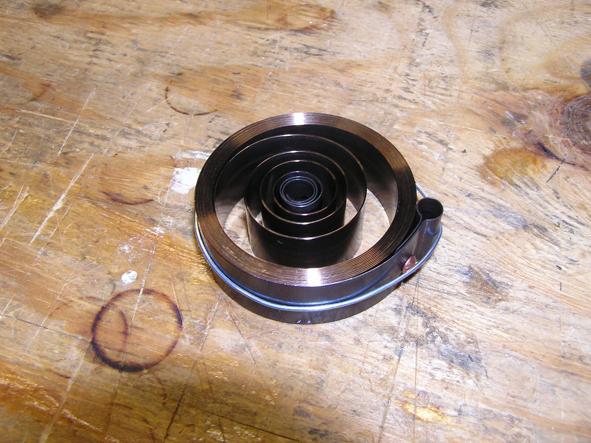
The next step is installing the new main springs. I have discovered that the springs in these old clocks have some real power. BE CAREFUL! The springs can suddenly release and hurt you or damage the clock movement. I left the steel wire that was wrapped around it on until it was in the clock. I would have liked to clean the new springs but I have no way of winding it up outside the clock. Maybe next time I’ll make a spring winder to help.
I installed the new springs and assembled & oiled the clock movement. Finally the clock is looking more like a clock again.
I made a test stand for the movement out of blocks of wood. It is important to make sure the movement is level so you can set the “beat” properly. I wound up the springs and cut off the safety wire. The clock is now ready to test. I attached the pendulum and watched it tick for about 1 minute then it stopped. I played with the clock for a while and could only get it to run for a few minutes. I noticed that the pendulum would lose its swing slowly until it stopped. It was not getting enough power to stay going. The striking gear train runs perfect so at least I that section is okay.
This part is where it starts getting hard. I do not know why the clock will not run. It could be weak main springs or too much friction in the gear train, or a dozen other reasons. It took me a good week to figure it out but finally I got it to run. It ended up being a problem with the shape of the verge. This clock has a “Half Deadbeat” escapement with and American style bent strip verge. I did more reading on escapements and how they work. Escapements like this one are only 50% efficient. That means that half of my springs torque is lost immediately at the escapement section. That’s not too good. The clock already has very little torque so an improper setup verge could reduce efficiency to 25% or worse. The clock will never run with this much loss in the power train. I discovered that my verge was all messed up and improperly shaped.
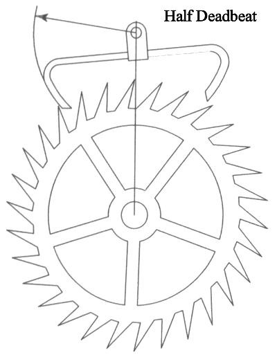
I took it off and ground on it until I got it to look like the verge in this diagram. The end points of the verge where it touches the escapement wheel teeth must be 45 degrees. I reassembled the escapement and tested out the clock again. This time it ran for several hours! I was pleased but it still stopped. I polished the verge and ground on it a bit more and success! The clock now runs for days and will unwind itself completely. The problem was all in the escapement. The verge is very sensitive to how its shaped and anything wrong with the angles will make it less efficient. It will not be able to transfer the proper spring power to the pendulum.
Here is a video of the escapement.
This is another video of the striking mechanism.
Video of the assembled clock striking the gong.
Hello Mike, I enjoyed your Blog and videos the photos are great.I’m like yourself interested in old mechanical stuff not made any more. Have 13 mantel clocks some go most don’t keen to get them going I have a lathe and drill mill and some tools. Your story has been insporational thanks easy to learn this way than books, you put it across realy good. I’m from New Zealand found your Blog by chance.
Thanks Ian Jones New Zealand.
Thanks for the comment. The hardest part is remembering how all the gears go together. Take many pictures so you can go back and look how they went together. Good luck! It is a lot of fun.
thank YOU SO MUCH FOR A GREAT ARTICLE.
Can you tell me what oil you used for the clock please,
regards
Bob
Hi, this probably sounds very basic but can you tell me, or show me how to take the clock face off the mechanism and how to remove it from the clock case.
Thankyou Mr. Freeman for a very informative article (which I absorbed like blotting paper does to ink!), much appreciate the time you have taken to put this on the web. From Sam Kirkbride, Lower Wye Valley, South Wales UK.
I am trying to find out the order of the gears. I have a movement that is in pieces and I know generally where things go, but a diagram of the order of parts would take the guess work out. Is there any way you can share that information with me please?
Loved your article but I have a deeper problem. The movement was taken apart by someone. I took pictures but after reassembling, I realized wheels were put in backwards, there is a single sided bushing with nothing in it and if that’s not enough this movement not only chimes but has a bell. It was put together wrong and I can’t figure it out… Yet. Wish someone had diagrams for specific movements to follow.
Hello Mike.
Great article. Loved seeing all the movement and the great job you did.
Have a couple of question I hope you can answer. I have the exact same clock (mine is 1927 also). It runs slow. loosing about 5 minutes an hour. Which way do you turn the adjustment (the pin on the face above the 12) to speed up the clock? My other question is on the same subject. The end of the key that you use for that adjustment is worn out. There are no markings on the key at all. Do you happen to know what sizes the key is so I can look for a replacement?
Thanks!
Mine are all marked with a F or S to show direction. So far all my clocks are the same. Turn it Clockwise for faster clock. Counter Clockwise for slower clock. Hope that helps. The adjustment key is standard 2mm. You can buy replacements cheap from http://www.timesavers.com
Thanks for sharing your experience! I have been trying to restore an old clock myself and have been struggling. I didn’t know that the tapered holes allow for a bit of gear shake. This is really useful for if I can’t quite get the alignment straight like you said. Thanks for sharing!
Yeah it really helps. None of my holes are perfectly centered every time. I have fixed 6 or so clocks now and they are still ticking away. I am still an amateur and just fix them for myself or friends.
Thanks for the interesting article for repairing an antique clock. I didn’t know that the pivot holes are tapered because it can reduce the friction on the pivot shaft. I’m kind of interested to learn if this is the case for all clocks or just smaller ones.
I have a broken click spring on the strike hammer side of the clock.Where can I get another one?