
I found the plans for this engine on the internet. It’s a Lamina flow engine based on the sterling cycle from what I have read. I honestly do not really know how this engine works but it runs on a external flame. It’s a really simple engine to build and there are tons of examples on YouTube.
Here is a Video of my engine running.
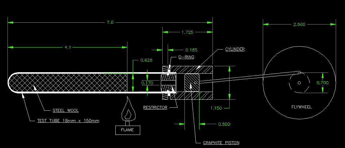

Click Image for larger view. This is a basic plan for the engine.
Building the Engine
These are the 4 main parts of the engine:
1. The piston & cylinder
2. Regenerator Tube
3. Flywheel
4. Flame
I used a small lathe & mill to make all the parts for this engine. A 4 jaw chuck is also useful if available.
Piston & Cylinder
The piston is made out of graphite. It’s the same material that is in a pencil. It gets all over your hands and is a mess to machine. It is about 0.625 inch diameter and 0.500 inch long. Graphite works exceptionally well in these sterling hot air type engines. The connecting rod is just a piece of 0.125 inch aluminum I cut with a band saw.
I used a small finish nail as a wrist pin. It is about 0.090 diameter and is very sloppy (my fault). There is a small hole in the side of the piston where the pin is inserted.
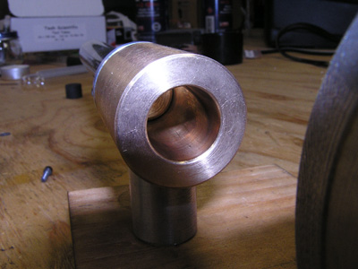
The cylinder is made of brass. I had some laying around and used it for this project. The cylinder bore has to be machined to a high precision. It has to be only a few ten thousands over the piston size. The cylinder must have a high mirror like polish. I made the cylinder first and then made the piston to fit. If it does not fit, the engine will not even run. I had this problem when I tried to use a test tube as a cylinder. The glass was out of round a few thousandths which made it impossible to get the engine to run.
Regenerator Tube
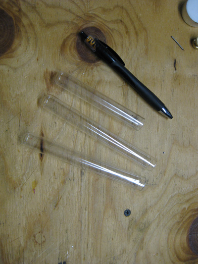
The regenerator tube is just a regular pyrex test tube I bought off Ebay. The tube needs to be filled with coarse steel wool. Size 18mm x 150mm long. I tried cutting one shorter and the engine did not run. I needed the full length tube. You can cut these tubes with a diamond wheel and a dremel if you have to. The diamond wheels are cheap and only cost a few dollars.
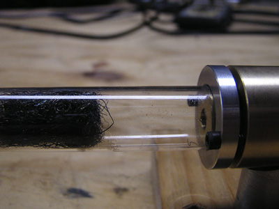
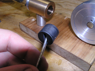
To hold the test tube to the cylinder, I used a method I saw several guys use on the YouTube videos. I counter bored the cylinder about .250″ deep to slip fit over the pyrex tube. I made a washer out of aluminum and tapped some 4-40 screws in the cylinder to hold the washer on. In between the cylinder and the washer is a rubber O-Ring that just fits over the tube. As you tighten the screws, the rubber gets squashed and tightens on the pyrex tube to hold it. This keeps the tube from cracking. I already cracked three tubes trying to hold it with a split clamp type of holder.
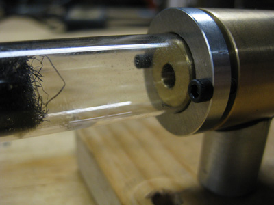
My engine needed a restrictor to separate the cylinder from the regenerator tube. This restrictor seems to be a bit
of a mystery because some engines do not seem to need one. The hole size is critical and ended up being .170 inch diameter on my setup. It is made of brass and has a rubber O-ring over it to keep it somewhat tight in there. I let the piston push it in there so that there is no space between the piston and this brass restrictor.
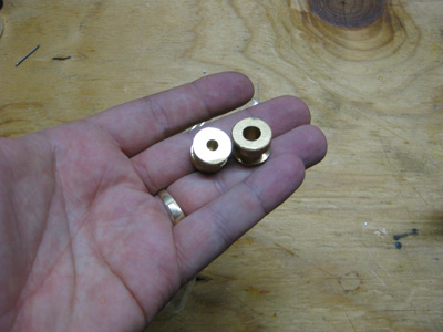 As you can see, I ended up making different sized restrictors until I found one that worked well. If it’s too big or too small, the engine is completely lifeless.
The Flywheel
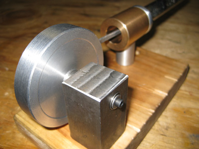
The flywheel is made out of scrap cold roll steel. It’s just a round wheel with a hole in it. The shaft is made of aluminum and I have two small bearings in the square pedestal to support the wheel & shaft. I thought about using brass bushings but the engine is very weak and needs bearings wherever I can fit them. I tapped the shaft 4-40 and used a socket cap screw to hold the flywheel tight to the bearings. It works well.
The Flame
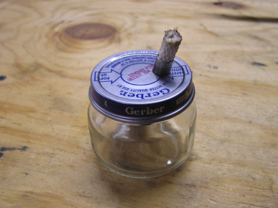
For the flame I just made an alcohol burner out of a baby food jar. I bought wick from the hardware store. It’s crude but it works well.
This engine was a huge pain in the ass to get to run. I wasted many evenings tinkering with it to figure it out. Everything about the engine seems to affect it somehow. The hole diameter in the restrictor, the placement of the flame, the type of steel wool, and the stroke of the piston.
The steel wool needs to be coarse so air can get into it. I tried some really fine steel wool (like 000) and the engine failed to run. The flame needs to be right on the edge of the steel wool or it will not work. I drilled several holes in the flywheel to allow me to change the piston stroke. For my setup, a stroke of 0.700 inch seems to work. I can change it a little bit and it still runs but not as fast. The engine can be flip start or you can make it rock back and forth like I did in the video.
Piston Fit:
This is really critical. To test if you have a good fit, place your thumb over one end of the cylinder bore. With the piston and connecting rod installed, try pulling the piston out of the cylinder. When you just about pull the piston out, let go of it. The piston should spring back to where it was with no friction. You can also feel the suction on your thumb. With your thumb over one end, the piston should gradually fall out of the cylinder very slowly as air leaks around it. Mine takes several minutes to fall out of the cylinder with my thumb over one end. If you can get a fit like that, you are set and the engine will run.
hi im just lookin around your websit its really cool!the lamina engien is wonderfull great job!i want to ask you some thing about the lamina engien fly wheel!how much is thick the fly wheel?? because you dont have on the plans!thanks darren malta europe
Hi,
Nice work man.
i was asking if you can send me one with higher speed to Egypt. because i failed to make the cylinder and piston get working together.
i can share my ideas with you and bring nice solution for life.
This is a excellent posting, I found your web page browsing bing for a related topic and came to this. I couldnt come across to much other info on this blog post, so it was nice to discover this one. I definitely will end up being back again to look at some other posts that you have another time.
hi;
this is really cool and works very well.
i’m gonna to build one like yours.
how much problem you faced for cylinder and piston?
is it hard or too expensive to order or make them?
what tolerance is needed?
tnx
Hello. I made this engine for my university project by taking resources from you. I’m having trouble running it. Although the dimensions are exactly the same. The brass cylinder size inside is not included in the autocad drawing. How many inches or millimeters? What are the important points I should pay attention to? Thanks.