
I had an extra Raspberry Pi laying around from when I ordered two of them a few months ago. I used the first one for a media center and it runs XBMC flawlessly allowing me to watch downloaded movies on my television. I pretty much have my entire DVD collection converted to DIVX format saved on my network for easy access. I could not find a use for the second one until I started to read about General Purpose Input / Output (GPIO) control on the Pi. Basically, the Raspberry Pi has an extra pin header for GPIO that can be controlled for switching things on and off and for reading sensors. It’s really pretty impressive for what this thing costs. I ran across a project called WEBIOPI which allows control of the GPIO from the internet. It is possible to control the Raspberry Pi remotely with any device connected to the internet.
I read about people connecting all sorts of things to their Pi. Everything from thermostats, lights, locks, to garage doors openers, cameras, and remote sensors. Some of these guys were controlling the Pi from their smartphone as well which really intrigued me.
I decided I wanted to control my garage door with my iPhone since my existing garage door opener is very short range and I wanted to be able to open it from the road. I also wanted to be able to tell if the door was left open. I hate it when I get 10 miles from house not remembering if I closed the garage door or not. There are several ways to connecting a Pi to your iPhone but I will explain how I did it with very little programming. I am not a programmer and have no real interest in complex programming so I avoid it when possible. Any smartphone will work with this setup. All you need is a web browser on your phone with a data plan.
First I will tell you this is not originally my idea. You can even buy commercial equipment from Sears that will do this for about $76 and an additional $20 yearly fee – that’s the easy way. I don’t know about you but I hate bills and fees and I also enjoy building my own stuff the hard way.
Equipment needed:
- Raspberry Pi – $25 (you will also need a 2Gb SD card and micro USB cell phone charger for it).
- Relay Shield from Radio Shack – $19
- Soldering equipment
- 50 feet of 2 conductor thermostat or door bell wire – $9
- Small proto circuit board, 1 kOhm & 10 kohm resistor
- Female jumper wires with header – $6
- Magnetic switch (the kind used on doors and windows by security companies).
- Your own existing network connecting to the internet with a router.
- Any smartphone with a web browser
I had most of this stuff laying around already. I only had to buy the relay shield & the 50 ft of wire. I am not going to explain in detail how to solder or how to setup the default operating system on the Raspberry Pi. There are many very well written tutorials on how to do both. My Raspberry Pi is running Raspbian downloaded from Here.
Once you have a Raspberry Pi running smoothly with raspbian, there are a few software packages that you need to install to make this work correctly.
I use a program called Putty to connect to my raspberry Pi remotely from another computer. You can also of course connect a monitor and keyboard directly to the Pi but I found this inconvenient since I had the Pi mounted by my router.
WebiOPi – Download here and save to your Raspberry Pi and install it manually if you want. You can skip this step and watch the video below to install automatically.
http://www.youtube.com/watch?v=6RaBz01pi4E This is a excellent video tutorial on how to install WebiOPi and configure it. I watched this video several times before I figured it all out. It’s all Linux so if you are like me and not very familiar with it, it can be challenging to use.
Here are the commands to get WebiOPi installed automatically.
Type the commands one at a time and wait until each finishes before going onto the next.
wget https://webiopi.googlecode.com/files/WebIOPi-0.6.0.tar.gz
tar xvzf WebIOPi-0.6.0.tar.gz
cd WebIOPi-0.6.0
sudo ./setup.sh
sudo update-rc.d webiopi defaults
That last command adds webiopi to the start up so when you reboot, its automatically started. You have to login to your Pi as “root” user so you have full access. The command “sudo” is needed prior to most commands because that calls for “root’ user privilege so you can install and configure the Pi. Linux is all about security so get used to it.
Now go to: http://localhost:8000/webiopi/ on your Pi’s browser and you will see the webpage below.
Default user is “webiopi” and password is “raspberry”
You should see this screen if it works properly:
You can also see it from any other computer on your network if you type in your Pi’s IP address into the address bar.
Example: http://192.168.1.10:8000/
If you watched the video, it explains how to do some simple CSS and HTML to make a simple web interface. I also disabled the password as explained in the video. I am pretty week when it comes to this stuff so I will provide my html file for you to use or modify. Feel free to change it around to suit your needs.
I used GPIO7 as the output and GPIO18 as the input (sensor for the door). You can use anyone you want.
Here is my file Index.html just right click and “save as”. It is just plain text. Save it to your working directory on your Pi.
So far, you should have a working Raspberry Pi with WebIoPi running on your network. At this point, you can only access the web control from your local network, it will not work outside your firewall yet. To get access to your Pi from anywhere on the net, you have to do a few things. I have to assume you have some basic network knowledge to get the next part working. I will explain as simply as I can but there are whole books written on this topic.
The problem with home networks is that your Internet provider will change your external IP address often. Mine changes every week or so and I have to have some way to let the “outside internet” know what my new number is.
12-26-13 Update:
I no longer use http://dyn.com/dns. They have a 30 day login requirement which is really annoying for their free members. It’s a shame since I have been using them for over 10 years. I now use a much better free DNS Service: http://freedns.afraid.org/ These guys are great and work perfect so far. I updated my instructions below to reflect the FreeDNS website.
First you need to sign up for a free account on http://freedns.afraid.org/ Log into your new account and add a “Subdomain” from the options on the left of the website. Pick an address from their thousands of available subdomains to use and remember it. Example: yourname.us.to Once you picked out a subdomain, go to the “Dynamic DNS” on the left menu. You should see your domain at the bottom with a note about it that says “1 Dynamic Update Candidates!”. There are several different links to the right of your domain and you want to click the “Wget script” and download this text file. This file will contain the 32 character token code that you need to paste into your router. It’s the security code that allows you to log into FreeDNS and update your IP address (your router does this automatically for you).
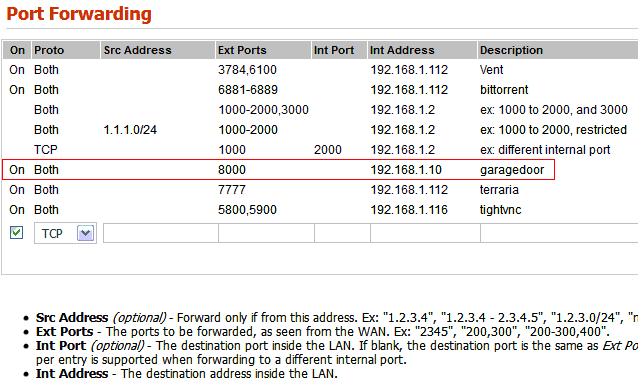
Next, you need to setup a “Port Forward” in your router. Every router is different. You need to forward port 8000 to your raspberry Pi address.
For example: My raspberry Pi uses 192.168.1.10 yours might be something else but it will be similar. So I want to go into my routers port forward section and forward requests for port 8000 to 192.168.1.10.
Below is what my routers port forward settings look like. I have many ports setup in there but the only one you need is Port 8000 which is highlighted in red.
The next thing you need to do is to setup your new FreeDNS account in your router. This is different on every router so you will have to look up the manual on your router and look up DNS services that are supported. I have a section just for this and its needed so that when your routers sees a IP address change, it will tell FreeDNS to update.
Below is what my router settings look like (I blacked out my own IP and Token code):
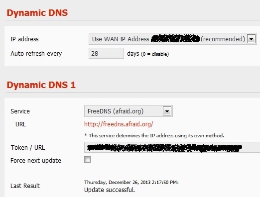
Every Linksys router I have used has this feature built in. I have also seen it on Netgear and Asus routers as well. I can’t say for sure if every router can do this but if yours can’t this will be a problem for you to access the web interface from outside. You should now be able to go to any computer including your iPhone and type in “yourname.us.to:8000″ and your WebIOPi interface should come up.
The next section explains how to build the actual interface between your Raspberry Pi and your garage door. The GPIO header is located on the Pi below:
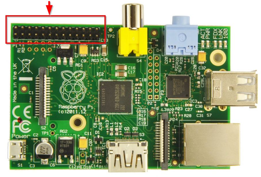
This header will be used to connect to your relay shield and to get +5v power and +3v power.
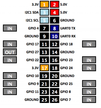
This is the pin out diagram which is off of the WEBioPI default page. It is extremely useful for verifying connections before you use your custom website. I pull this up on my iPhone for testing all the time. It’s called “GPIO Header” on the default WebioPi site. I setup some prototype test circuits to test the raspberry pi before I spent money on the relay shield. This step is not necessary but I wanted to understand how it all worked before I set it up.
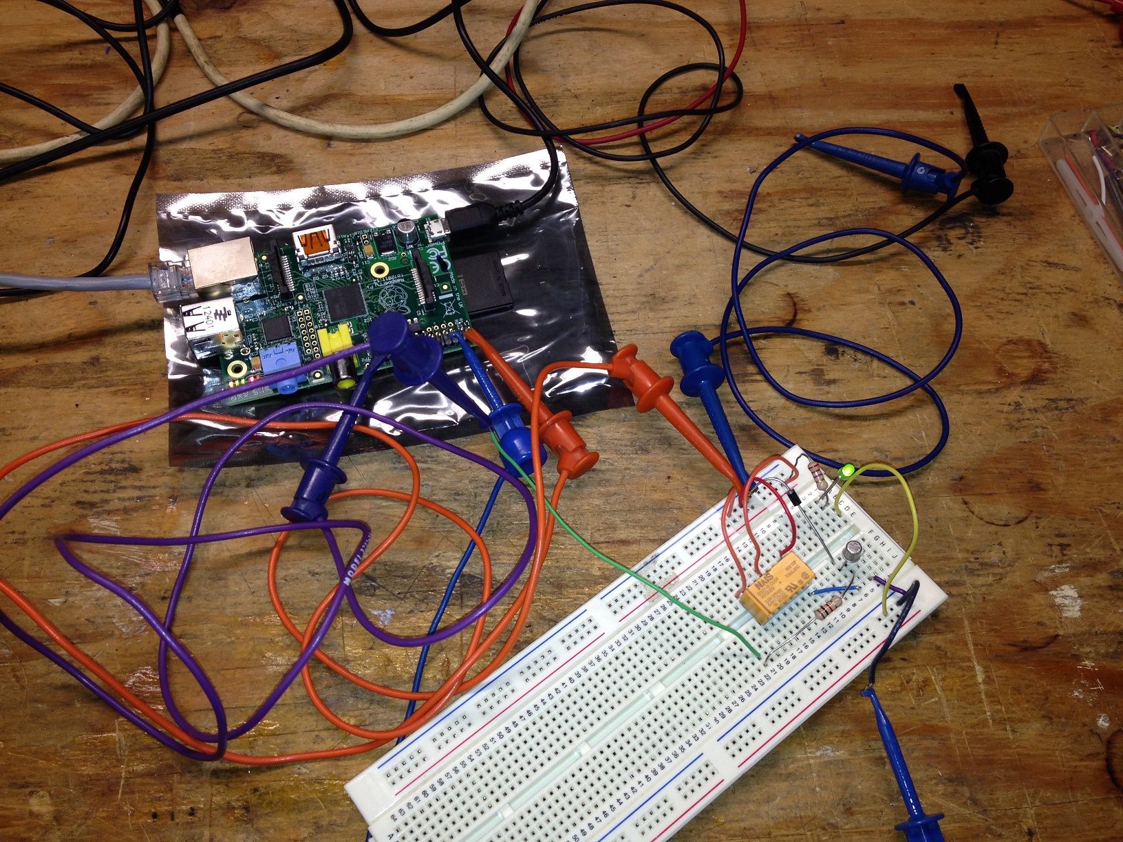
I ended up using GPIO7 as the interface with the garage door. Basically all you need to do is touch the two wires that go to the garage door switch together to make the door activate. The PI will accomplish this by using a relay as a switch to short the two wires together.
This is the circuit I used to connect to my garage door. The screw terminals go to the two wires that connect your garage door button in the garage. You can build your own circuit if you want, but I just bought a “Relay Shield” for $20 from Radio Shack. It was nice and had 4 relays that I can use for other stuff if I want to later.
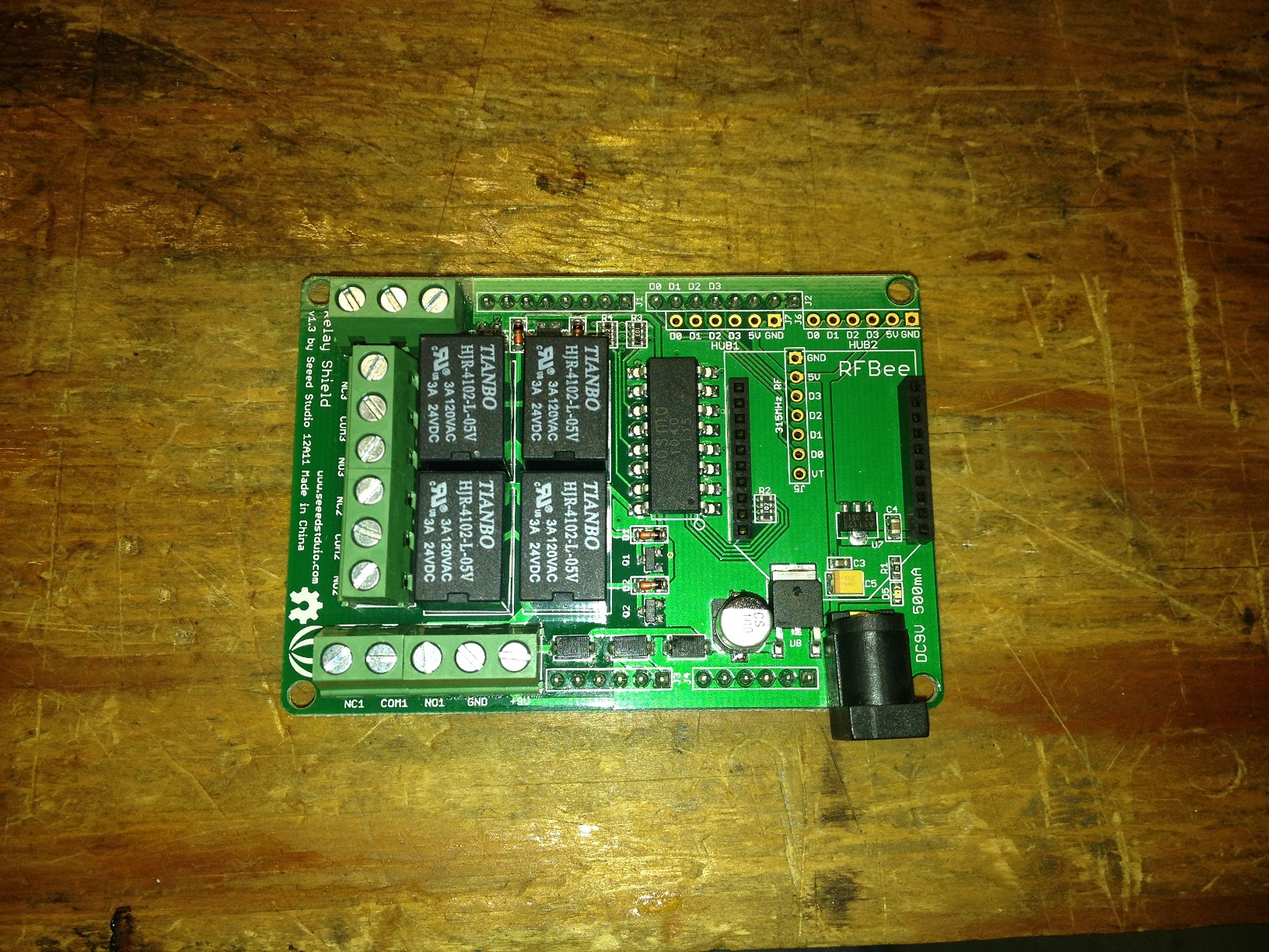
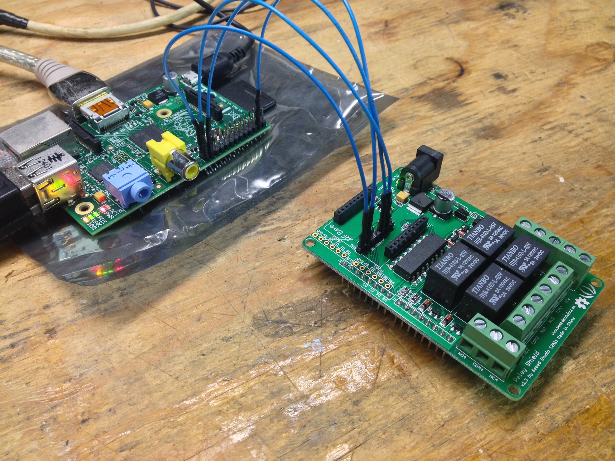
This is the Relay Shield. Its awesome and will run off the +5v from the Raspberry Pi with no problems. No need to power it separately.
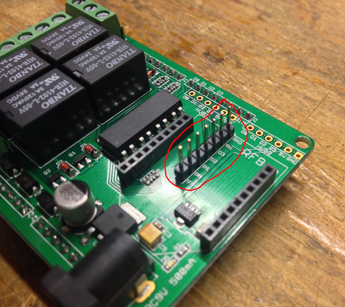
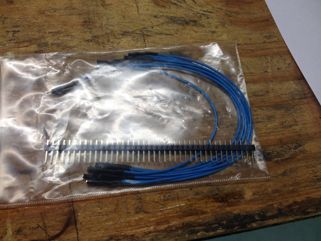
I soldered a header connector very similar to the Raspberry Pi to the relay shield as shown. The header connector is included with the blue jumper packet. To connect the relay shield to the raspberry pi requires these little blue jumpers also available in a pack of 10 with a header connector for $5. They are cheaper on-line but I did not want to wait. We are going to use only 3 pins (GND, +5V, D0).
They connect by pushing them on the header pins as shown. No soldering required for the blue jumper wires. Connect “D0” to “PIN26”, “5v” to “PIN2”, and “”GND” to “PIN25”. I know my image shows 4 wires, but you only need 3. I was using the 4th to test another relay. That’s it for the relay. You should be able to press the GPIO7 button on the WEBiOPi website and your should hear the relay “click”.
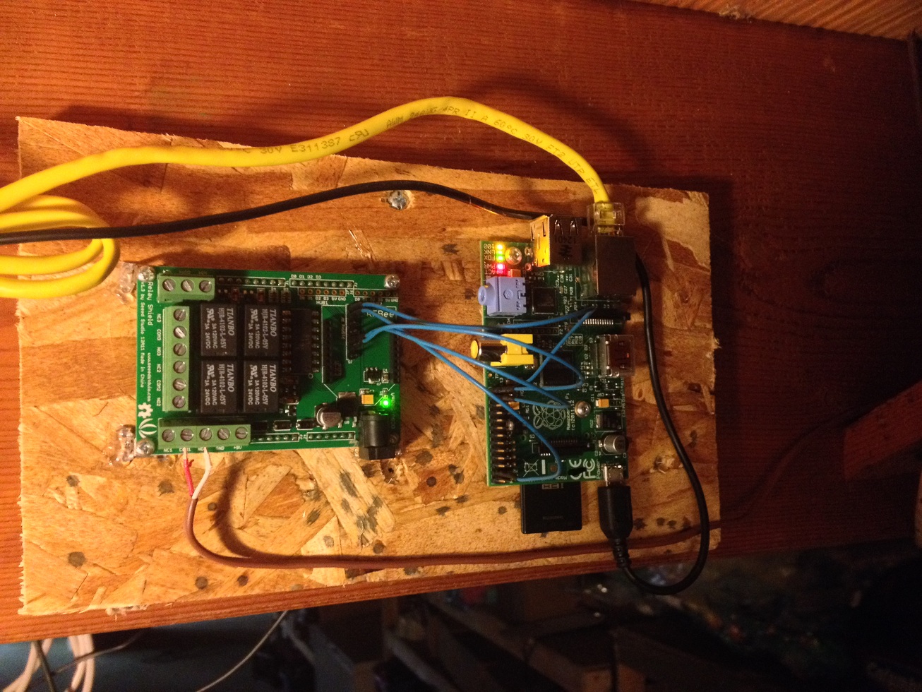
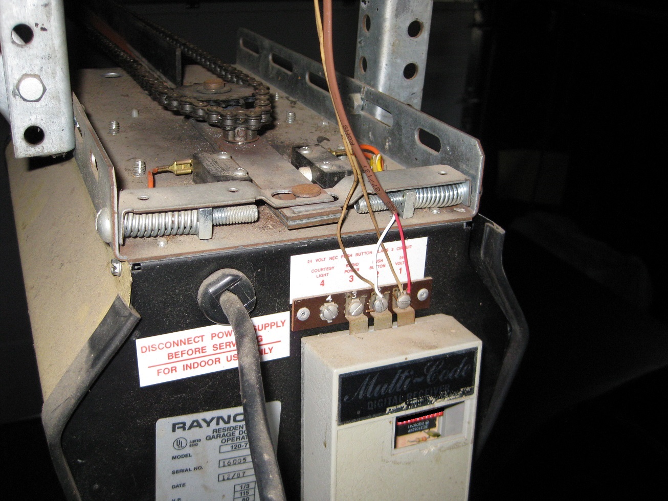
I ended up mounting the whole assembly very close to the my router in my basement. I ran 30ft of thermostat wire from the garage door opener to the raspberry pi. Connect the two garage door wires to “COM1” and “N01”. There is no polarity so it does not matter which way you connect them. You can see below that I connected the thermostat wire from the Pi to the same connections on the opener that my push button opener is connected to.
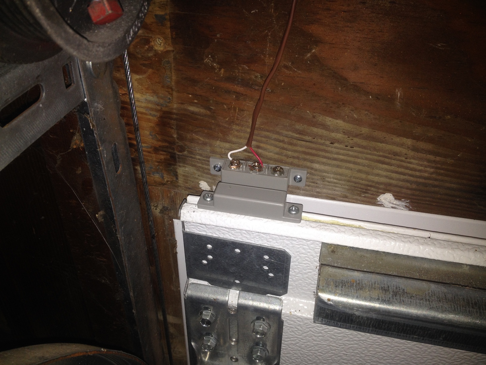
The garage door sensor is all that is left. The sensor was a bit tricky and I did some thinking for a while on the best way to get the raspberry pi to know if the door was open or not. I needed a switch that the door would trigger when open. The perfect switch is one of those cheap little magnet switches that security companies use on doors and windows. You mount the magnet on the door, and when the door moves the magnet away from the switch, the switch will open or close depending on how you wire it up. I bought one for a few dollars from my local electrical hardware store in town.
You can’t just connect the magnet switch to the raspberry pi. Unfortunately, you can’t use the relay shield for this either. I had to build another circuit that would interface with the raspberry pi. The GPIO pins are very sensitive and can easily get destroyed if you apply too much voltage to them. They also have this problem of “floating” between hi and low when you set a pin to a “input”. They act all goofy so you need to ground them out with a resistor to make them behave properly.
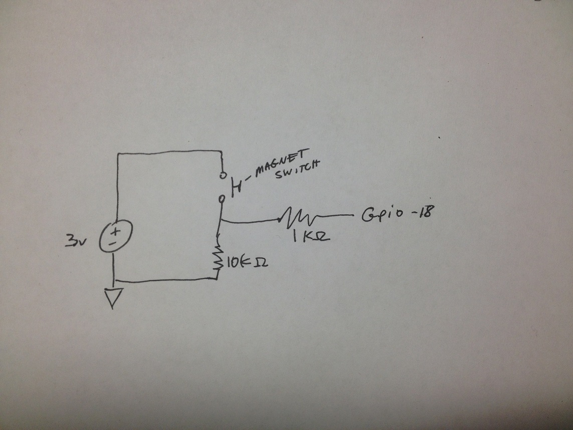
I used this circuit to connect my magnet switch to GPIO-18 or “PIN12” on the raspberry pi. Its very simple and only requires a few parts: one 10Kohm resistor, one 1Kohm resistor, a 6 pin header from your blue jumper wire kit you bought from Radio shack, and a small proto soldering board. I have a ton of old proto boards from other projects I built.
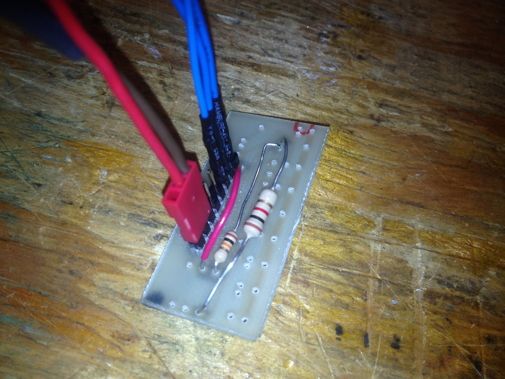
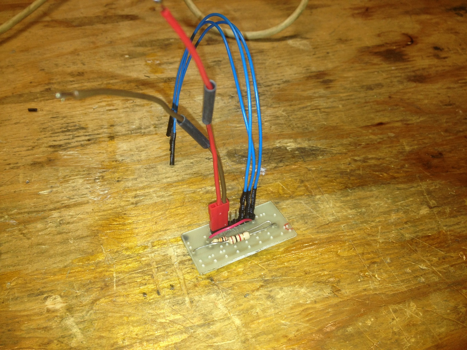
The red and tan wires go to the magnet switch. The 3 blue jumper wires go to “GPIO-18”, “+3v”, and “Ground” on the raspberry pi.
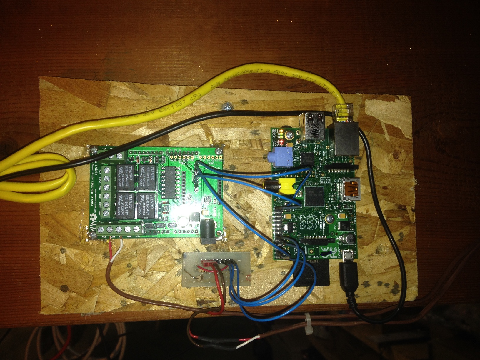
Here is the complete setup. It works pretty good and has no hesitation between the phone and the garage door so far. This project is complicated but doable if you take your time.
There are three main parts to this project:
1. Getting the Raspberry Pi setup on your network with WebIOPi working
2. Connecting the garage door and Relay Shield to the Pi
3. Connecting the door sensor.
I did not move onto the next phase until I got the previous one working 100%. If you try to do all three and once, you will get frustrated and kick your cat or kids if you have them.
I’ll make a video of the door working this week. More to come.
Thanks for reading the super long post.
Mike
I’m going to try this out this week! I liked your solution since I’m not much of a programmer either and I liked the idea of being able to access it from down the road instead of having to pull into the driveway and wait for my phone to connect to the wifi. Also, great idea with the door open or closed detector. Any update on that video?
Do you really need to use the 1K and 10K resistors? Can,t you just use a GPIO what has an internal pullup resistor like GPIO2 or GPIO3?
Tried that but the GPIO kept floating high or low until I used the 10k.
@Jay; Sadly, when using webiopi there is no way to use the internal pull-ups/downs on the gpio pins.
Mike, it is always better to use a pull-up instead of a pull-down. That way you don’t have voltage running through the switch and you can have the electronics further away. I did this same project last year for the same reason. But, I have several garage doors. I’m adding a driveway sensor so my pi will send a text message whenever a car pulls into my driveway.
I would love to know how you make it send the text. I want to connect mine to my sump pump so that if overflows I will get a text.
I have also the rpi controlling the garage but no interface, I have to ssh into it to run the relay. I have the rpi send me a txt whenever the door opens or closes and also if its open more than X minutes it also sends me a txt. And for added security if its open more than X minutes and it detects motion it takes a picture and sends it.
For the txt I used a script to send emails from python through gmail. depending on your carrier you should be able to send emails to 7021234567@mms.att.net and receive them on your cell as txt. The second half of the address changes but I believe it works on all others carriers. they are all diffrent you have to check what works for you.
Felix
First, good article.
Second, WEBIOPi is now version 0.7.0
Third, I also got ‘fed-up’ with dny.com/dns
and went to afraid.org.
Works great, and easy to update when my ISPs
IP changes.
Many thanks for putting this together, it’s helped me tremendously in understanding the basic relationship between HTML, Webgpio and the GPIO pins. I added a third button and changed the first to a toggle so that I now have toggle / open / close , the toggle button still shows the status as did your original design. I’m actually using this as the basis for turning my heating on and off so the momentary action of the original needs to be permanent as opposed to transitory.
First of all thank you for the effort of sharing this. I also based my project on this. Some time has past and I came along some challenges which I was able to solve. In the future I want to expand this to Domoticz. Then you can use a native app for it.
Here are my notes on this:
1. WebiOPi-0.7.1 still does not officially support 2B models. Not all 40 pins are shown and the the webbuttons do nothing. There is a patch for this. This one worked for me, but there are others.
Link: https://www.raspberrypi.org/forums/viewtopic.php?f=63&t=98981 This post: by danjperron » Wed Jan 06, 2016 8:22 pm
2. The drawing for the magnet contact circuit was not clear to me. This is a similair project which has a better drawing I think: http://www.driscocity.com/idiots-guide-to-a-raspberry-pi-garage-door-opener/ . Drawing: http://www.driscocity.com/wp-content/uploads/2014/05/sensorwiring.jpg Also see comments on this one too. A lot of new information.
3. Here is some direct info on how to change the password. http://webiopi.trouch.com/PASSWORD.html sudo webiopi-passwd
You can also store the password in the link itself like: http://user:pass@192.168.2.29:8000/macros/ArmIt. That is easier for mobile devices. I use a very long and hard to remember password so it is safe even if someone sees it accidentely.
4. I wanted to have push notifications when some action happened. I found this which works good after some tweaking:
http://www.richlynch.com/2013/07/27/pi_garage_alert_1/ There is also a part 2 http://www.richlynch.com/2013/08/04/pi_garage_alert_2/. I use pushbullet and mail notification. This worked good, except that e-mail didnt work anymore after rebooting. Check this for that: http://askubuntu.com/questions/157154/how-do-i-include-lines-in-resolv-conf-that-wont-get-lost-on-reboot and http://www.cyberciti.biz/faq/dhclient-etcresolvconf-hooks/. Dont remember which one did the trick.
5. Improving the custom site. I wanted to protect the custom site for accidental pushes, because I always use it on my phone. After searching for a long time I found a solution. This is what I did:
– Removed this from the custom index.html > Door Status
– renamed it to index1.html
– Used this code for the new index.html:
… Code of point 5 was cut off. This is the code:
Code:
//
//
Cant get HMTL code on. Please contact me mike for the code.
I have a new chamberlain HD210 model that does not have a dry contact type wall button – confirmed by their reps. When I short the two wall wires the GDO does not respond but my previous craftsman used to. I had tried to install a Sonoff WiFi switch, but due to that reason it cannot work the GDO either. Basically no relays can get the GDO to respond and I my options are directed to their branded internet gateway. I know there are DIYers who have implemented self solutions with this types of wet contacts but I haven’t found one yet, I am at the end of my wits. My question first is, is there a way to implement this or a similar solution with a non dry contact type GDO?
Hi Rscode,
Can you please send me your code?
Code is already posted on the site. index.txt is the file and I have a link about halfway down.
Hi, I read about your project from a couple of others that have done something similar (https://www.driscocity.com/idiots-guide-to-a-raspberry-pi-garage-door-opener/ and https://github.com/nebhead/garage-zero). Thanks for the ideas.
Regarding the sensor input, I don’t see why you need both the 1k and the 10k resistors. You only need the 10k as a pull up from what I see. The closed switch will ground the input directly.