
Eliminating buzzing and high pitch squeals in your home audio equipment can be a pain. 90% of it is probably the result of a “Ground Loop” as was in my case. This situation can occur when you have two or more electronic devices interconnected by either video or audio cables and they develop a slight electrical difference in their grounding with the power system. The voltage difference can be heard as a buzz or squeal in the speakers and if its large enough, it can damage your equipment. I ran into this problem when I connected a PlayStation 2 video game system to my home stereo and a DLP projector. I could hear a horrendous squeal in my speakers that was as loud as the normal games sounds. Surprisingly, the noise was not between my PS2 and the stereo. It was from the projector. The voltage was back feeding from the video ground of the projector through the PS2 audio grounds and then to my stereo. Crazy…
To eliminate this, you need to somehow separate the grounds so that there is no fighting for ground between the electronics. This is accomplished with a “Ground Loop Isolator”. These can be purchased for less than $15 online or from an electronics store. Today is Sunday, everything is closed, and I don’t feel like waiting a week for an online order.
It is possible to make one if you have enough junk around the house like I do. I had everything I needed to build one in various boxes around the basement and it took me about 30 minutes to assemble.
What you need:
- Soldering Iron
- Solder (flux core)
- De-solder tool
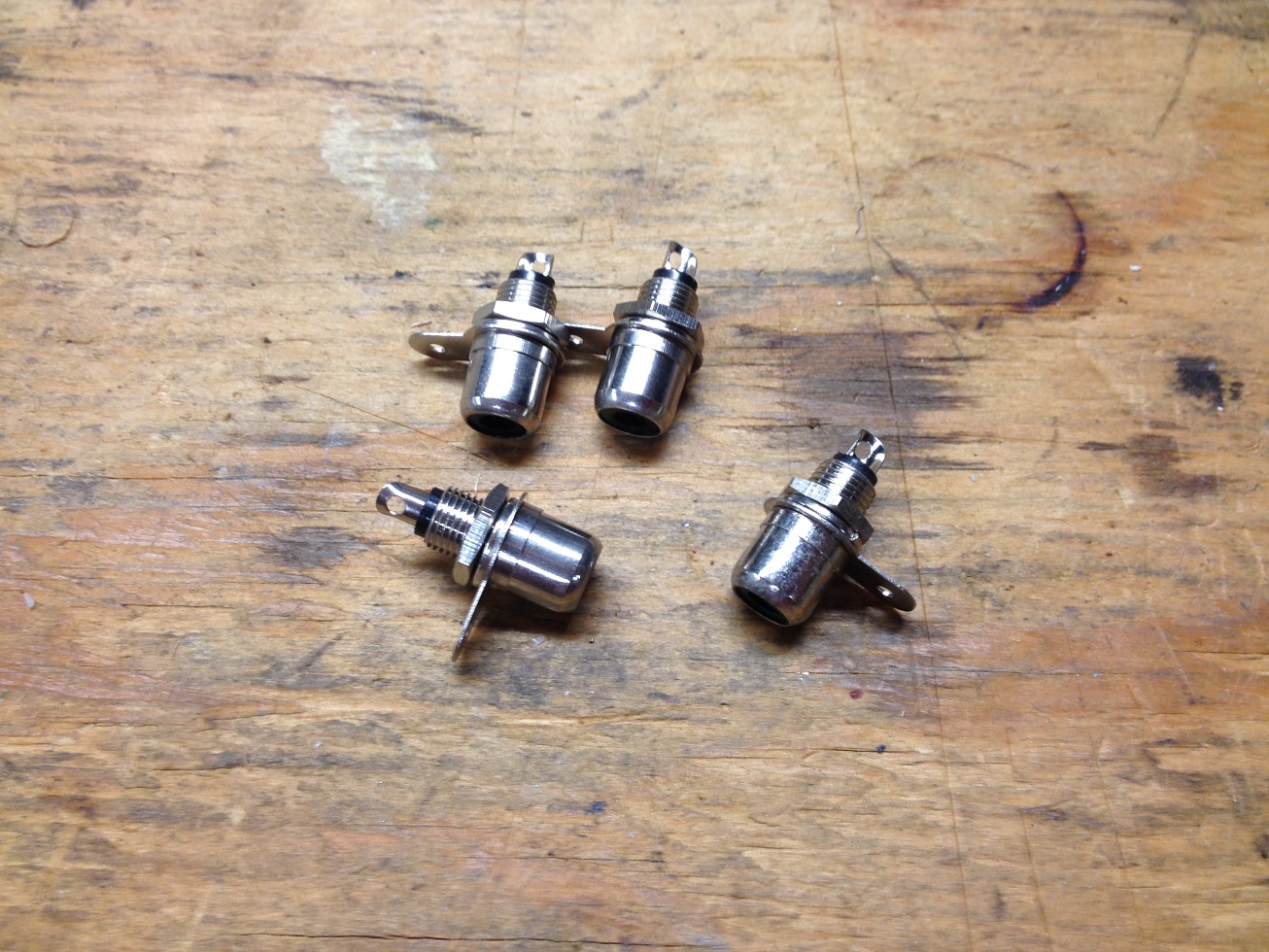
- 4 RCA femal plugs
- small project box
- 6 inch of small wire 16 gage will work
- 2 old PC modems
Find 2 old PC modems. I have a box full of old PC parts and it was no problem for me to locate them. You will be using the modems isolation transformer since its perfect for our intended use. They are mostly the same and are 1:1 ratio 600 ohm.
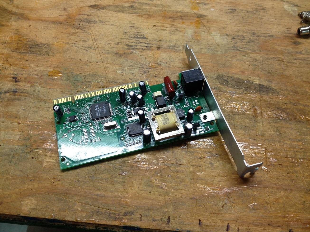
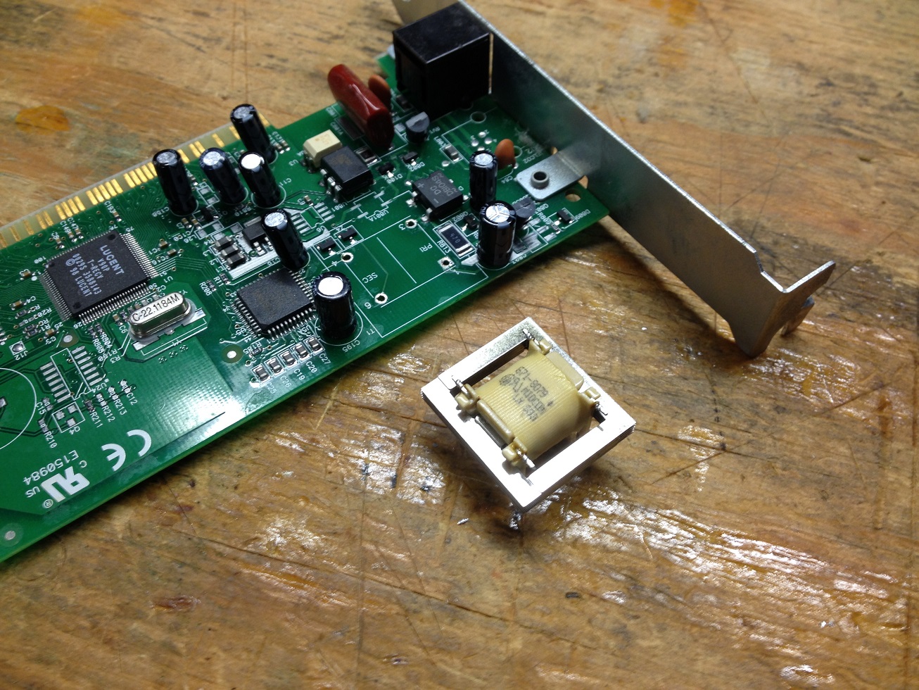
The big square thing on the modem is the isolation transformer you want to remove. Some look different but they are easy to spot. Using a de-solder tool and your solder pin, simply un solder the 4 legs and remove.
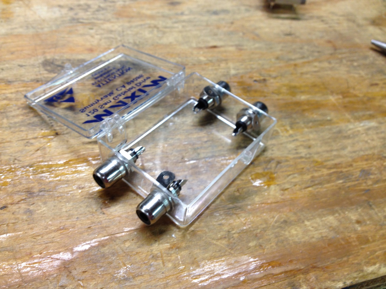
Get your connectors and project box ready. I drilled 4 holes in my project box to allow easy access to the plugs.
Next, you need to understand the circuit you will be building. It’s simple and shown below. You need one of these circuits per channel (right and left audio).
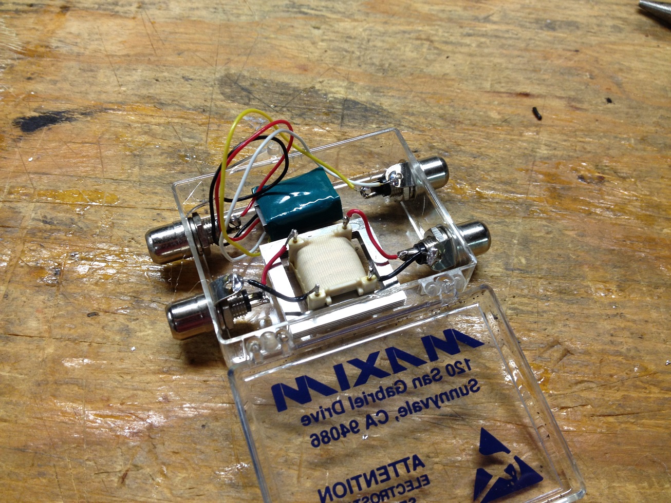
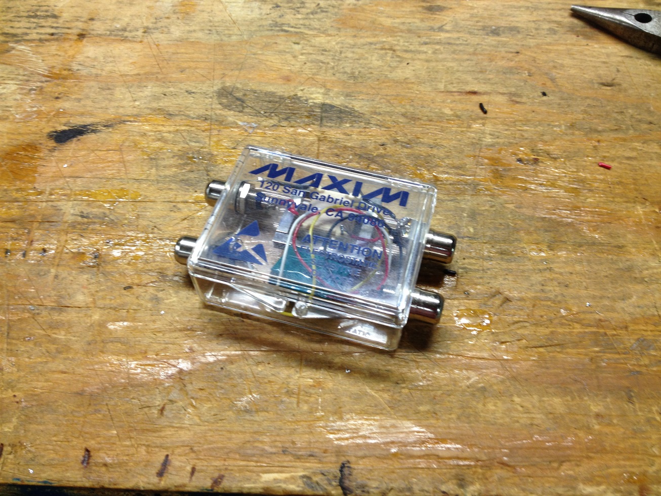
Solder each transformer as shown below. I ended up using two different transformers and it worked great. I used some hot glue to keep the transformers from moving around in my small box. You can use anything you have laying around. Transformers have no polarity so you just need to make sure you are using the correct coil pairs. Use an Ohm meter (or multi-meter) to identify the coil leads. It will display as a short on the multi-meter when you cross a coil.

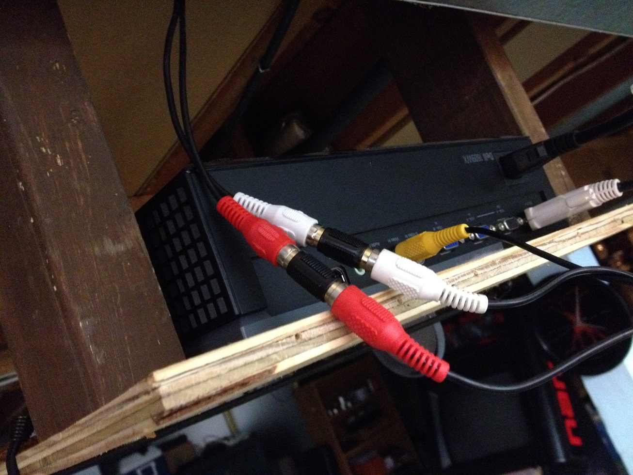
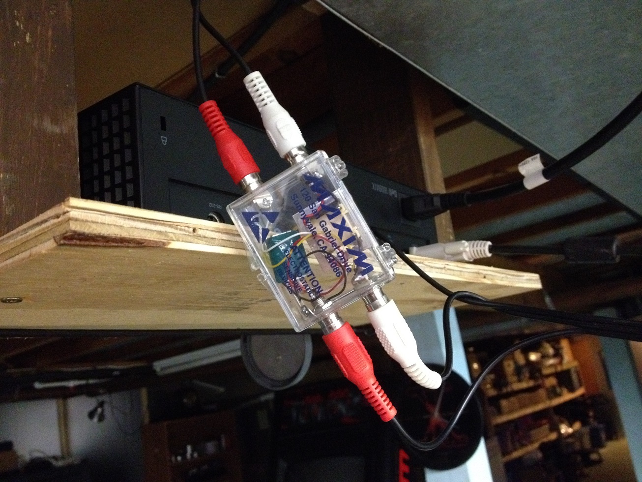
Installation is simple. Just install in the audio cables before the stereo. I installed mine between the PlayStation 2 and the stereo.
That’s it. I now have crystal clear sound. I have not noticed any degradation of the sound quality. The bass still shakes the room like it did before.
Hello i am building a powder coating oven that will have to stove elements in it i have the cd101 pid controller and a 240 ssr and i am lost on how to wire this thing can you help me please I got the main power to it and the TC hooked up just not sure what out post to use to run into my relay and how if you can help it would be great thanks, John
Hey thanks alot. Your totally awesome. Old modems never had a use but they sure do now lol.
This is wickid mate! Had no idea it was so simple. I run a small project recording studio and this could save me quite a bit of money. Can’t wait to dig out a few modems at work.Cheers!
can i do this with antenna cable?
Those transformers are very fragile, I busted 3 of them just when removing them 🙁
I’m going to buy a commercially assembled one…
so guys be careful
I built this ground loop isolator using 1:1 600 ohm audio transformers to help eliminate hum on a DIY bluetooth speaker. I ran the speaker wires across the transformer wires where this was continuity and measured the resistance at about 120 ohms. Unfortunately, the audio output from the speakers was severely reduced. Did I do something wrong? Thank you.
You shouldn’t connect the transformers to the powered output. You should connect them across the line level input. The noise is reduced at that side of things. If you have noise on output and no noise after input then you most likely have another issue.
Thank you bro.
Works great. Crystal Clear Sound 🙂
How could this be wired to a three pin two phase xlr connection? Would I just split the ground output and send it to both hot wires? I’m planning ahead, the near feild monitors I’ll be getting have a ballanced input, and are bi amped self powered monitors so it is a line level xlr going to them. I don’t have the money to buy oxygen free silver Mogami cabels just yet but nead a high resolution signal. I also intend to get this furman (below) with linear filtering, I think that may eliminate the need for these but I’m not positive.
https://www.axemusic.com/furman-plplusc-power-conditioner-with-led-light-racks-and-voltometer.html
Thank you bro !
Thanks for the idea! Got me fixing my noise in my car by reusing some transformers from a old ethernet card.
Thank you very much Mike Freeman. It’s very easy solution to do, and it gave the old modem a nice way to die in peace :))
The interference it’s all gone, i use in some power amplifier speaker, which i added bluetooth module.
Greetings from Romania.
Great article. I’m looking for this solution for long time. The problem is the 1:1 audio transformer is very expensive. But you have shown me the easiest way to get it.
THanks again for your efforts.
Mong Phan
I tried a simple build (similar to the one you posted above) using dual 600:600 (ohm) “Perma-Alloy” isolation transformers. These were originally intended for use in an R2R style DAC and for converting the XLR signal to RCA. My requirements only need me to isolate the dual outputs of my function generator for calibrating a Potomac AA-51. The function generator currently shares the ground on both of the BNC shields and this is the issue. The easiest solution should be isolation transformers, it was my first thought and that is how I got to your site!
So, when I checked the output of the transformers the sine wave from my MHS-5200A (25 MHz) was heavily distorted. I was only passing a 1kHz signal with a 2.82Vp-p (1Vrms) amplitude. I checked each winding bobbin for continuity with the tiny bare wire as well as with the connection wires at each end of my circuit. I couldn’t detect any problems.
I’m not that well read on isolation transformers, but considering they are 1:1 turn ratio, you should be able to use them pointing in either direction, right? I also noticed that each of my transformers had 2 pair of bobbins in common, like you see on the primary side of transformers that have both 110V and 220V input capabilities.
I did what I have done before many times when I see 4 inputs on a transformer, I combined the pairs of bobbins with a common connection. Then I ran each of my signal wires to said bobbins. I did the same thing on the other side, as it also had 4 bobbins. The only other option was to leave them alone and only hook up to 2 of the 4 and output on 2 of the 4. There is one last possible explanation, but I doubt it, could it be meant to handle a stereo signal, as with XLR carrying a + and – signal?
I’d appreciate any advice you can give as to where I may have gone wrong or maybe something else I can check. I also run my own website, mainly focused at audio HW (www.Hallmanlabs.com) and I’m looking for other sites to network with, if that interest you at all shoot me an email Great site and great article
what is the name of the little blue box in the picture / next to the travo
what is the name of the little blue box in the picture / next to the travo
Also a trafo
Why do you need a transformer on the positive wire? Isn’t it only the ground wire that needs to be isolated?
Not arguing, just trying to understand, thanks.
Please disregard, my mistake.
Came across this, tried it (with isolators from a Sony motherboard) and the sound was quite different; soprano sound with no bass. How did u ome to settle on the modem isolators vs others? Is there a power requirement?
This DIY Ground Loop Isolator project is exactly what I needed! I’ve been struggling with annoying hum in my audio setup for ages, and your step-by-step instructions are super clear. Can’t wait to give it a try! Thanks for sharing!
Great post! I never realized how crucial a ground loop isolator was for my setup. The step-by-step instructions were super helpful, and I’m excited to try this out to improve my audio quality. Thanks for sharing!